OVerview
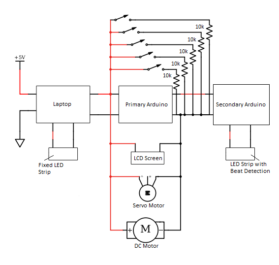
Our electrical system helps to transport signals given by the software system to produce the experience that our Soundcrystal offers. From ensuring the signals are sufficient, to flashing our LEDs to the music, our electrical system ensures that the right information is getting where it needs to go within the system.
Power Diagram
LED s
|
Our SoundCrystal has three LED strips. One of them is permanently lit and is purely aesthetic. It is powered from a USB port on our laptop. The other two are something special.
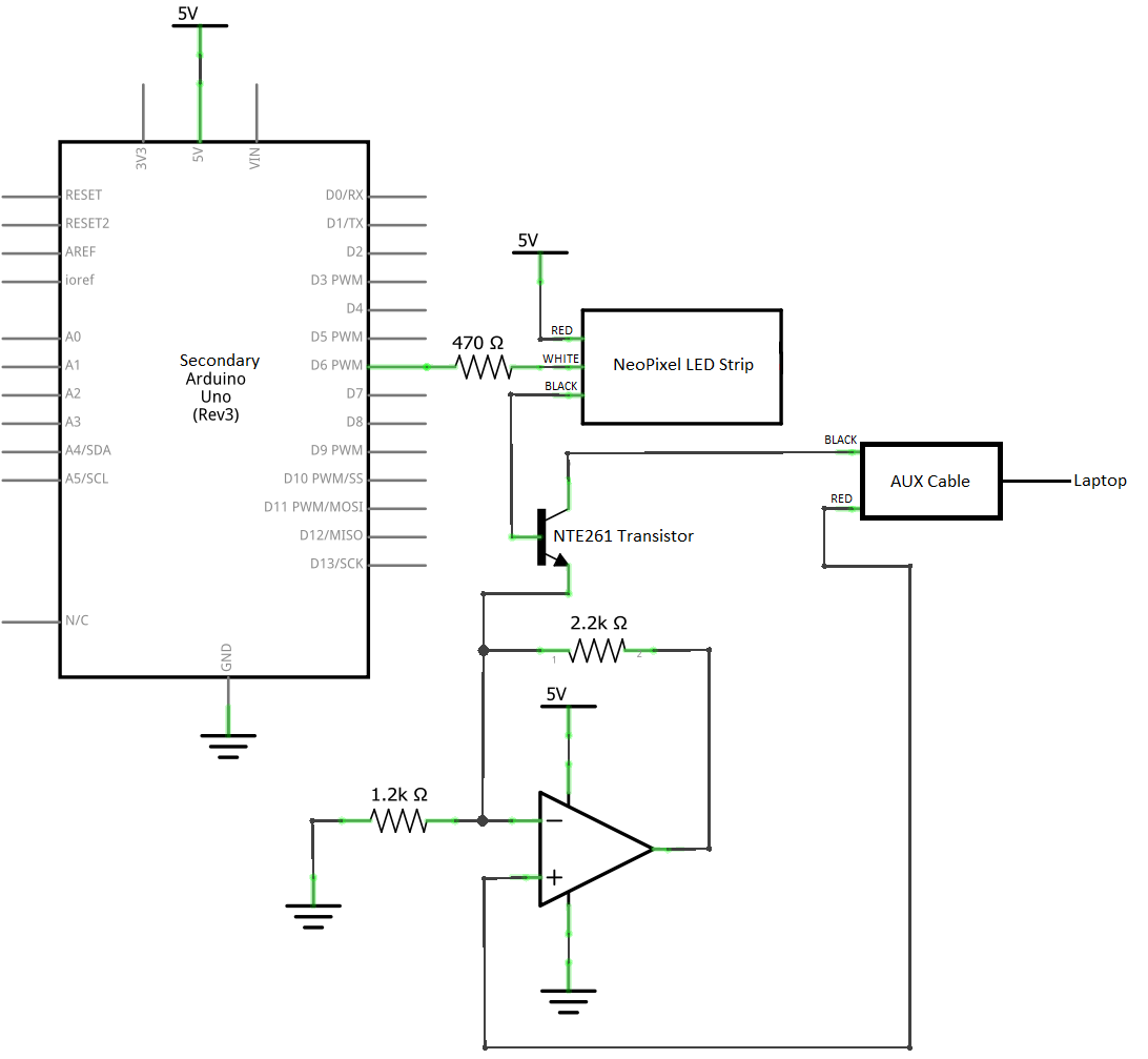
We use two 30-LED neopixel strips for our live beat detection. To begin, we connect the red power wire to 5V on the Arduino, and the white data wire through a 470 ohm resistor to Digital Pin 6. This allows us to power and control the color setting of each individual LED on both strips. The black ground wire, however, has two potential locations. It either connects to Arduino ground, for setting its color, or it connects to the middle output pin of our transistor. We use a non-inverting amplifying circuit to process the input signal from our auxiliary input. This signal is then sent to the transistor, where it connects to the LED ground and amplifies changes in voltage, due to the beat of the song. As a result, we get an awesome effect of the lights flashing along to the music! |
Buttons
|
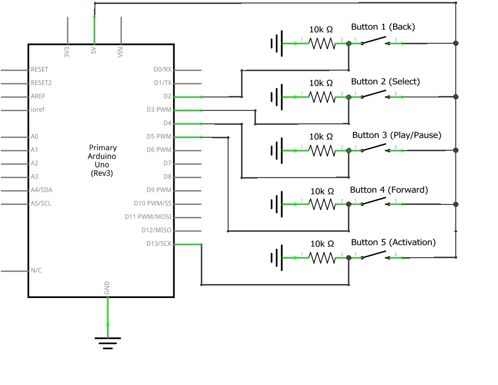
The music player in the SoundCrystal receives all of its input from the buttons, including when to activate, and what song to select, load, and play.
Wiring for the buttons is simple. A button is connected to 5V and a 10K ohm pull-down resistor to ground. A data pin is connected between the button and resistor to tell the Arduino when a button has been pressed (e.g.- the switch is closed and the data pin reads a voltage). |
LCD Display
|
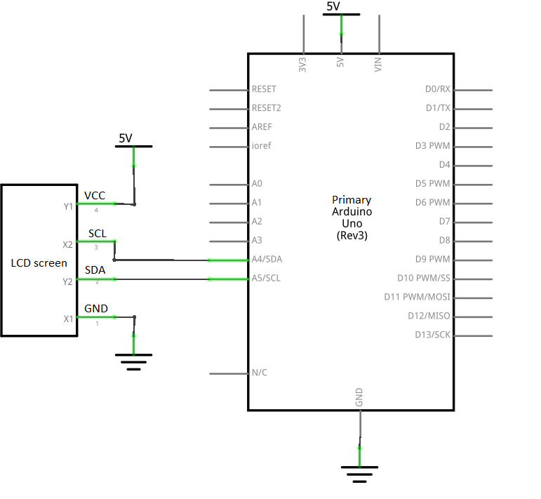
The LCD display is used to display which songs are playing. It was a very straightforward piece of electronic equipment with four wires: One for power, one for ground and two for data communication. When our SoundCrystal is plugged in, the display flashes four times and displays our jukebox's name "SoundCrystal". After a couple of seconds, it prompts the user to insert a marble to activate song selection and playback. Once it has been activated, it then displays the fist song on the song list. When the back and forward buttons are pressed, the LCD screen scrolls through the song list. When the load and play/pause buttons are clicked, the screen briefly displays "Loading", "Playing" or "Paused".
|
Record needle and spininer
|
|
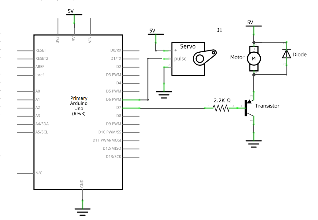
The record needle and spinner provide a visual aid to the SoundCrystal's audience, and add a little bit of traditional jukebox flair: when a song is playing, the record needle hits the record, which begins to spin.
We originally had the DC motor simply connected to a digital pin for voltage input. That didn't work, and we found that a DC motor would need a bit of help to receive information from the Arduino telling it when to run. A 5V needs to supply voltage to the Arduino, but in order to tell it when to run, we need a transistor: an electrically-operated switch. This alone will let the system work, but might create a reverse current, so we use a diode to ensure that the current only runs one way through the system. The resistor simply helps to ensure the right amount of current is flowing through this circuit. The record needle is actuated by an Arduino-controlled servo. The Arduino communicates with the servo using pulse width modulation (PWM) over a digital pin. 5V is supplied to the servo by the Arduino. |
Create a free web site with Weebly

