Mechanical System
Building, Balancing, Rotating
Iterations
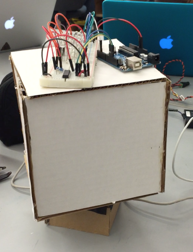
Sprint 1
Throughout the length of the project the mechanical system underwent many iterations. Once the project was decided to be an LED display, we chose the shape of the display to be a cube. We also knew we wanted to have the display spinning. For our first prototype we built a cardboard cube sitting on top of a smaller box which housed the motor. This gave us a representation of the our initial idea of a spinning cube.
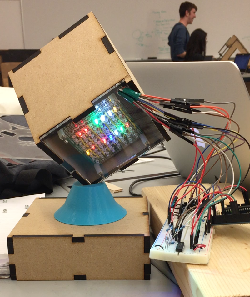
Sprint 2
For the next iteration we decided to increase the difficulty of our initial mechanical system. While the previous idea was only able to showcase five sides of the cube, we wanted to make it so that all six sides of the cube with LEDs could be seen. We accomplished this by designing a 3D printed piece that enabled the cube to balance on its vertex. We were then able to design the cube on Solidworks and laser cut it out of MDF to give a more polished presentation. Through this iteration we also decided that the final cube would be made entirely out of laser cut acrylic to best showcase the LED matrices.
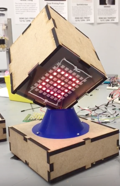
Sprint 3 and Final Work
The next step was to make the new design spin. After running into some balancing issues we decided it would be best to provide support from below by using posts made out of delrin, which has a low enough friction coefficient with acrylic. Some other small but effective changes that were made included adding a hole in the center of the 3D printed piece to allow wires connecting to the LED matrices to fall through to the Arduino. We also were able to redesign the faces of the cubes so that they had holes to match up with those on the LED matrices for easy attachment. We attached the matrices to the acrylic using screws and nuts.
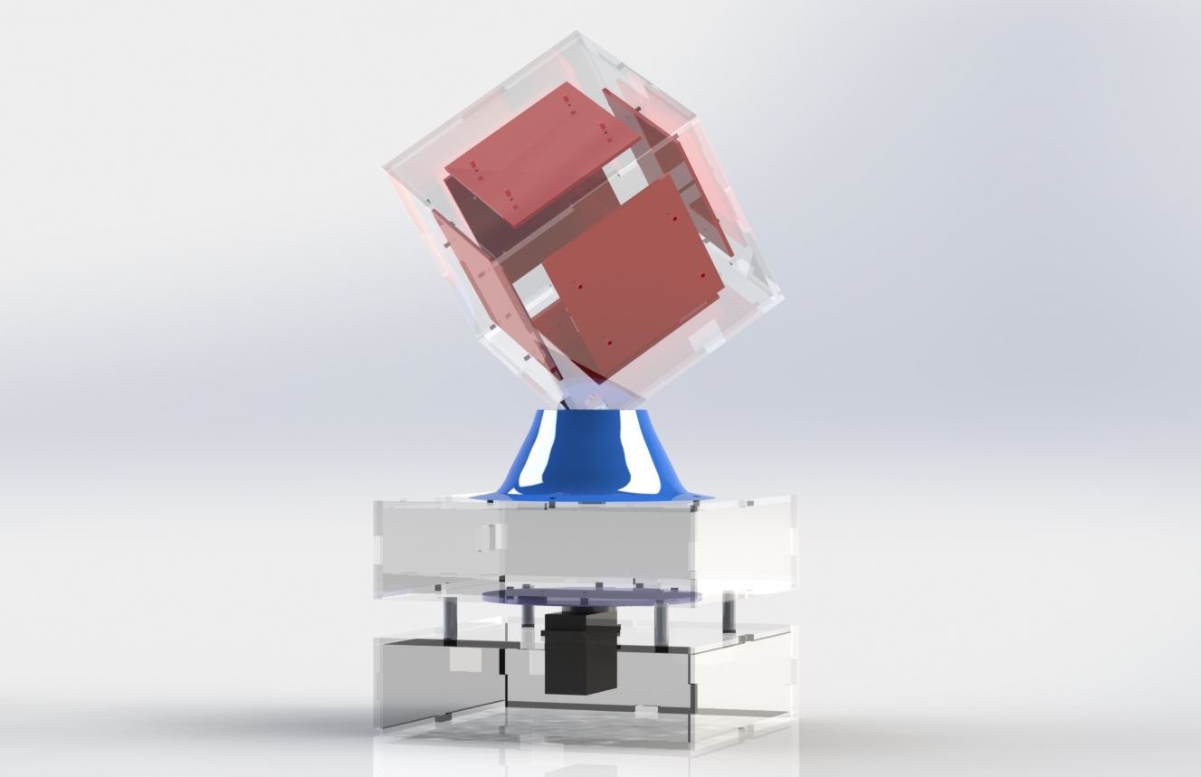
Breakdown of Cube Lite
Outer Material
Each wall of Cube Lite is made of 1/8 inch clear acrylic. This was a clear desicion for the top layer of our cube to allow for the LEDs to shine without obstruction, but we also chose to use clear acrylic for the boxes that house the Arduinos and wires. Our design decision to allow for visualization came because we wanted people viewing Cube Lite to understand the technology of how Cube Lite works.
Top - LED Cube
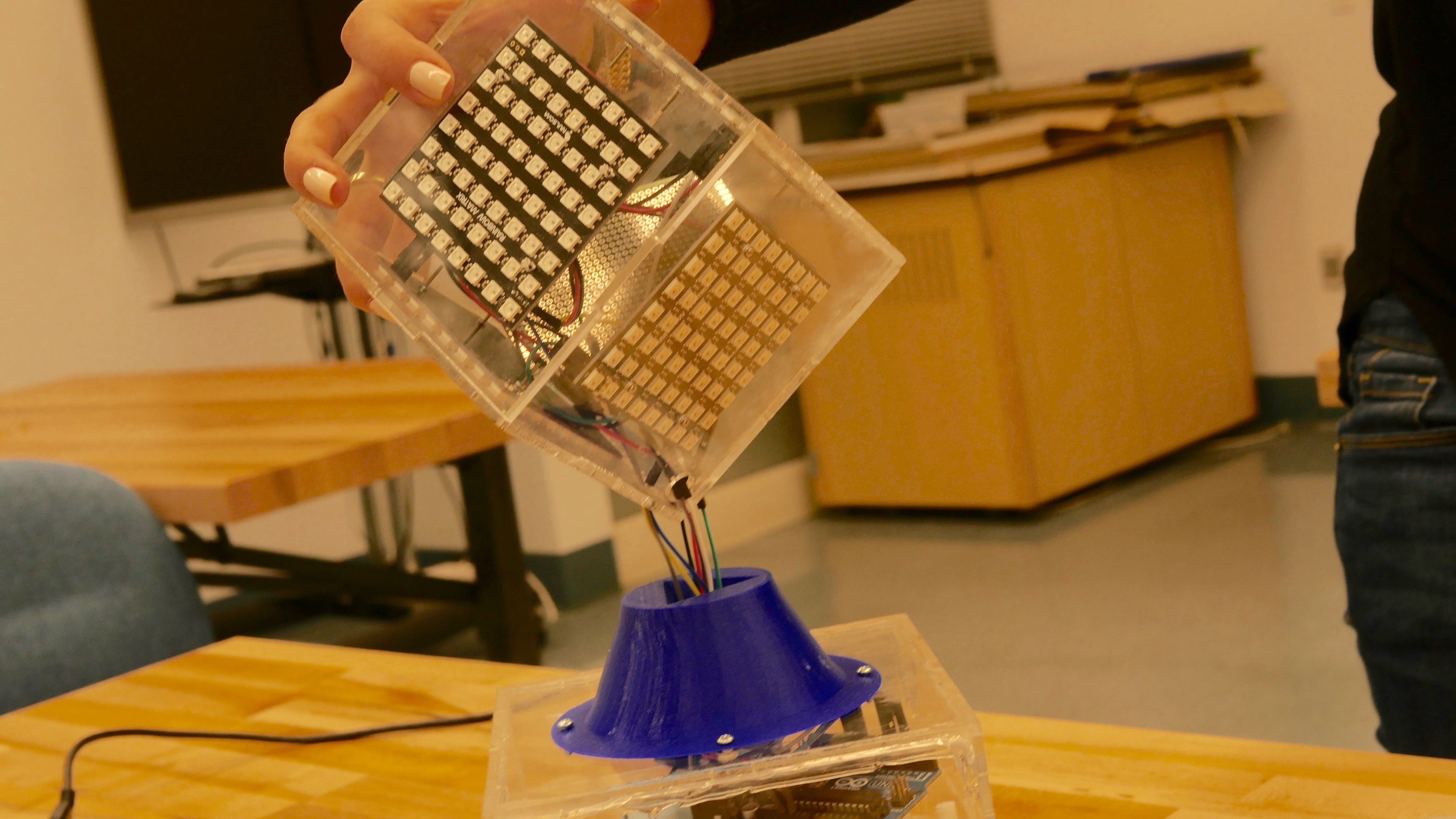
The top box and main attraction is our LED cube. Each face of the cube is made of a 4.5x4.5 inch sheet of acrylic with an LED matrix attached on the inside of the sheet. The wires run through holes in the bottom of the vertex, and then through a hole in the 3D printed piece to get to the controlling Arduino.
Middle - Beat Control and Cube Holder
The middle box of Cube Lite houses the Arduino controlling the LEDs. On the top plate of the middle box, we attached a 3D printed piece with an embedded prism and hole in the bottom to allow for the LED cube to sit flush in this piece without falling over while on it's vertex. There is a hole for a USB cable cut in one of the sides. We attached a 3D printed circle to the middle box, which is attached to a motor to increase surface area and driving capability for the spinning mechanism.
Bottom - Spin Control and Support
The bottom box houses the servo and the Arduino that drives the servo. In the top plate, we cut out a rectangle the dimensions of the servo and pressed the rotational shaft of the servo into the motor attachment on the bottom plate of the middle box. We use a rotational position servo to spin the cube. The servo rotates a maximum of 180 degrees. We chose to use this servo with only 180º rotation rather than continuous rotation because the Arduino controlling the LED patterns needs to remain connected to a computer. This way, the USB cable would not get wrapped around the cube. Four delrin rods are attached press-fit and then secured into holes in the corners of the top plate. These rods extend to the bottom of the middle box and provide stability when the cube turns. The delrin and the acrylic have a low coefficient of friction, so the rods do not impede any movement.