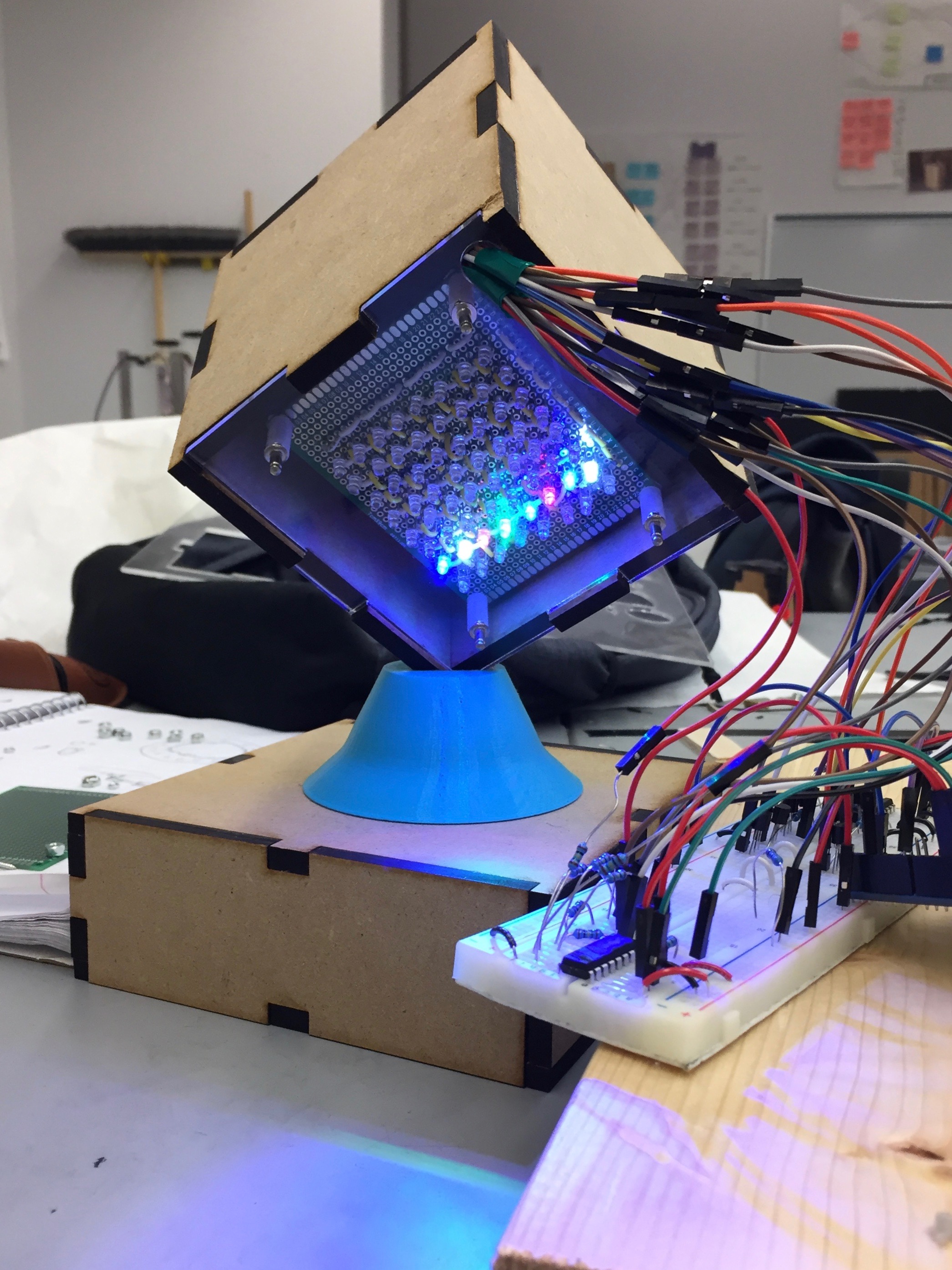
Electrical System
8x8 LED Matrices
LED Matrices
Our electrical system consists of an Arduino UNO that powers six 8x8 LED matrices: one matrix for each face of the cube. Every LED is individually accessable from the Arduino to allow the for the display of interesting light patterns. When we first began our project, we knew we had two options for making these matrices: making them ourselves or buying pre-made matrices.
DIY Matrix
We first decided to make our own test matrix because we believed we would not learn much from simply purchasing pre-made parts. In implementing our own circuit from scratch, we had the opportunity to make multiple design decisions and practice creating clean, modular circuits.
In creating our matrix, we advanced in a way that focused on incremental changes. We planned to progress this way so that if we ran into a bug, we could squash it early by knowing from where it originated. We started by designing our circuit on paper. After finalizing our design, we started our actual implementation by creating a 2x2 version of our matrix on a breadboard, and once we confirmed it worked, expanded to a 4x4 matrix on a breadboard. Our design was therefore scalable and successful, so we moved to soldering the matrix onto a protoboard. We started with a 2x2, tested, expanded to a 3x3, texted, and repeated until we had our full 8x8 matrix.
Multiplexing
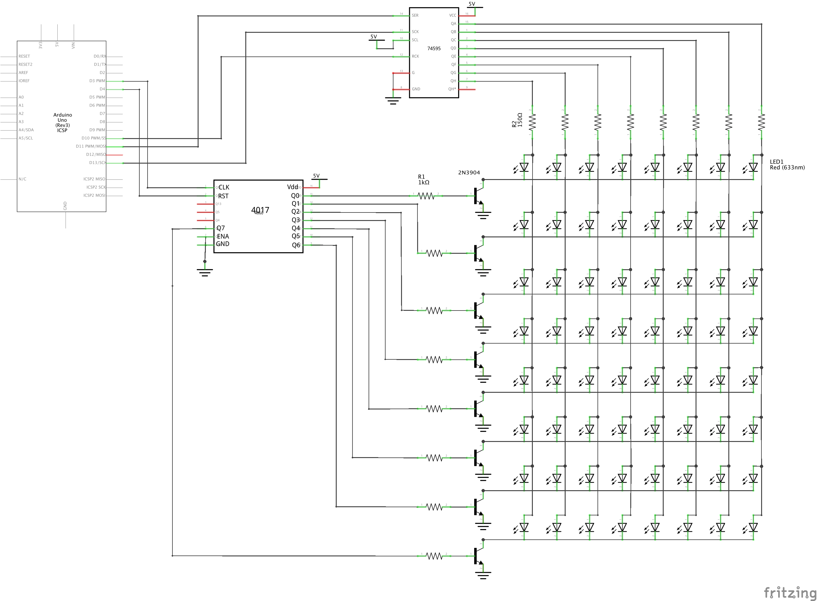
The first challenge we encountered was being able to individually light up every LED. Using one Arduino pin per LED would not be an option; every face has 64 LEDs, meaning the total cube would need 384 pins. The Arduino UNO only has 6 I/O PWM pins, making this system implausible. The design we decided on was to multiplex the 64 LEDs of a face together.
In our circuit, the LEDs of one face are layed out in their intuitive 8x8 square. The anodes of the LEDs in every column are connected in parallel, and the cathodes of every row are also connected in parallel. Each row of cathodes is also connected to the collector of a BJT 2N3904 NPN transistor whose emitter is grounded. This transistor acts as a switch: when a voltage is applied to the base of the transistor, the switch is closed and current can flow through the transistor's channel, causing the cathodes to be grounded and thus allowing the LEDs to light up given the appropriate voltage at the anode. When a voltage is not applied to the base, current cannot flow through the channel (like an open switch) and the LEDs cannot turn on. A resistor is needed at the base of the transistor to limit the current to the base.
We used a CD4017BE decade counter to set the 8 rows of cathodes using only 2 Arduino pins. The 4017 loops through counting from 0-9 by having the corresponding output pin (of which there are 10) be set to HIGH, a positive voltage. We had the 4017 count from 0-7, by using the RESET pin, in order to loop through the 8 rows of cathodes. Even though this design only allows for one row of LEDs to light up at a time, the 4017 counts quickly enough that, to the human eye, all rows of LEDs appear lit at the same time due to persistence of vision.
We used a SN74HC595N 8-bit SIPO shift register to set the columns of anodes with 3 Arduino pins: output pins to set the serial input, clock, and latch of the shift register. By shifting in the 8-bit binary number corresponding to the visual pattern we want displayed on the columns of a given row (for example 10000001 to have only the first and last columns lit), the shift register outputs every bit to a different one of its 8 output pins. The shift regiser outputs either a logical HIGH or LOW, corresponding to the +5V and 0V that are connected to its Vdd and GND pins, when a 1 or 0 is shifted out. The LEDs, however, can only operate below a certain current, so a current limiting resistor is needed between every output and LED column.
Thus, when a row is grounded by the 4017, the columns are set to the corresponding column configuration for that row. Overall, the matrix will have the appearance of being lit with whatever sequence of binary numbers are set for the columns of every row.
Soldering
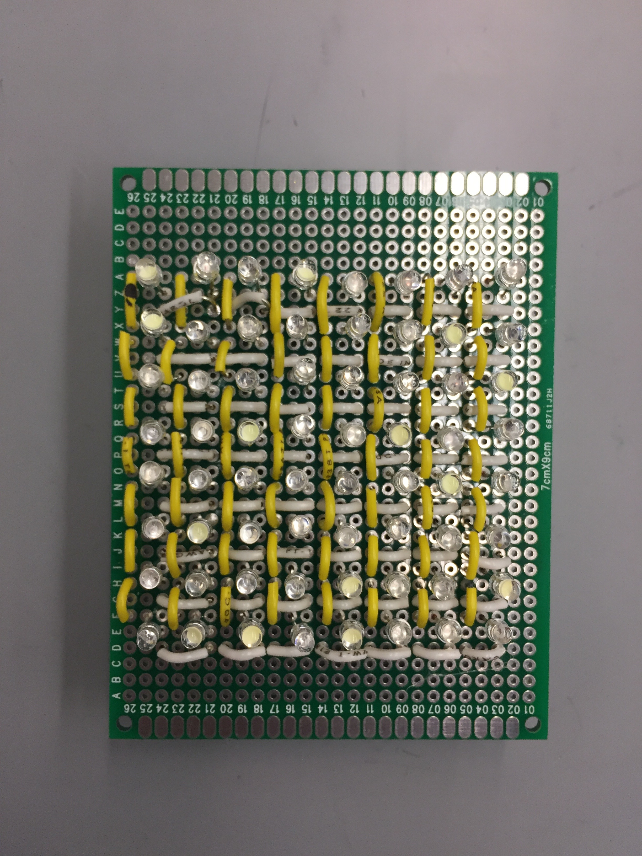
After designing and testing our circuit, we soldered a full 8x8 LED matrix onto a protoboard. We used CR150311E0004 LEDs and randomly chose which colors to use out of a selection of white, yellow, red, blue, and green. However, after soldering the 64 LEDs of one face, we realized that soldering over 300 more LEDs in order to have all 6 faces would not be conducive to learning. The main focus of making our own matrices was to learn to deisign the circuit and test it through actual implementation, thus soldering more matrices would give us minimal additional benefit.
If we had continued making our own matrices, a next step of implementation would have been to daisy chain the 6 SN74HC595N shift registers of the 6 faces together and use SPI communication to send the column information to one shift register that would then send the appropriate data to the subsequent shift registers. Furthermore, we only soldered the LEDs onto a protoboard; we left the shift register, decade counter, transistors, and resistors on the breadboard. Another possible continuation of the DIY matrix would be to move these extra parts of the circuit to their own protoboard that could be stored inside of Cube Lite separately from the LEDs. However, in soldering the LED matrix, we realized that the number of connections from these "outer" components to the LEDs themselves might be problematic if DIY matrices were used for all 6 cube faces. There are 16 such wires per matrix, so successfully routing the wires and storing the "outer" components might not be feasible without expanding the physical size of Cube Lite.
Production Quality Matrices
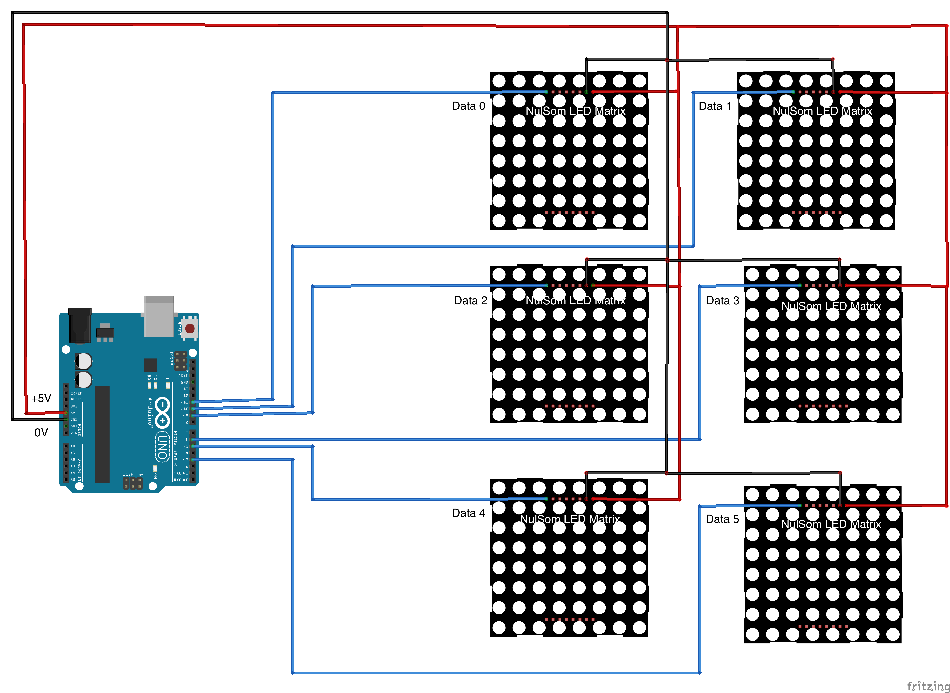
We decided to use NulSom LED matrices for the faces of our cube. Using these pre-made matrices not only allowed us to focus on the aspects of our project that had more opportunities for learning, but also enabled Cube Lite to have a more professional look while keeping the individually-addressable LED functionality that we desired.
In order to use a NulSom matrix, we had to solder pins for +5V, ground, and input data into the board at specified locations (pins on the board were specifically labeled). Each of the six matrices' input data pin was connected to one of the Arduino's PWM Digital I/O pins and the matrices also recieved +5V and ground from the Arduino.
Not captured in the circuit diagram is the wiring challenge of connecting all 6 matrices to +5V and GND from the Arduino. What starts as 2 Arduino pins turns into 12 wires in total. This large number of connections is problematic because all wires connecting the Arduino to the matrices have to travel from the middle box to the cube through the small holes in the 3D printed mount and cube vertex. Thus, in order to decrease the number of wires that go through these holes, in the center of the cube is a protoboard that splits the two +5V and GND wires from the Arduino into the necessary two wires per matrix. This design allows just the necessary two +5V and GND wires (along with each matrix's data input wire, for a total of 8 wires) to go through the hole, with still getting the functionality that we need.
The NulSom matrices are also capable of being daisy chained together. If we wanted to expand our project to have multiple cubes or more matrices, we would have looked into daisy chaining to reduce the number of Arduino pins used.
Servo for Rotating Mechanical System
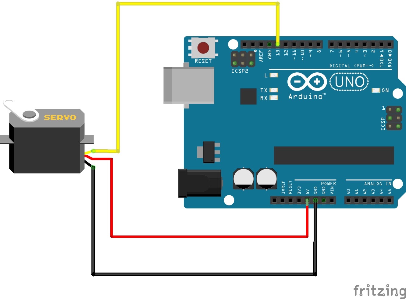
A servo was also used to drive the rotation of the mechanical cube system. This electrical subsystem connects the servo to one of the Digital I/O pins of the Arduino to allow the servo to spin 180 degrees in either direction.