Mechanical

Introduction
The mechanical system was a major part of this project because it was responsible for the physical movement of the M&Ms into positions that make up an image. The team’s concept of what this would look like changed dramatically over time, and the prototypes reflected that development. At first, the team’s minimum viable product was a 2-axis gantry that would create edible black and white images from sprinkles. The stretch goal was photorealism, a pretty device, user friendliness, and use of LEDs. The minimum viable product changed in the last sprint when the team admitted the scope of creating a working dispenser that handled tiny sprinkles was too large. In the last sprint the team decided that the stretch goals were all out of reach other than our goal to make the project aesthetically pleasing. The team changed sprinkles to full size M&Ms, and our stretch goal was reflected only partially in the aesthetic of our device. Still, the final mechanical design successfully met the modified requirements for a minimum viable product, so the team was happy with the outcome. Each version of the CAD model is available on GrabCAD, but if you're too lazy to click on the link, here's a summary of every prototype on the path to our final design:
(Often, developments in the gantry and dispenser systems happened separately, so are described as such in the prototype descriptions.)
Prototype 1
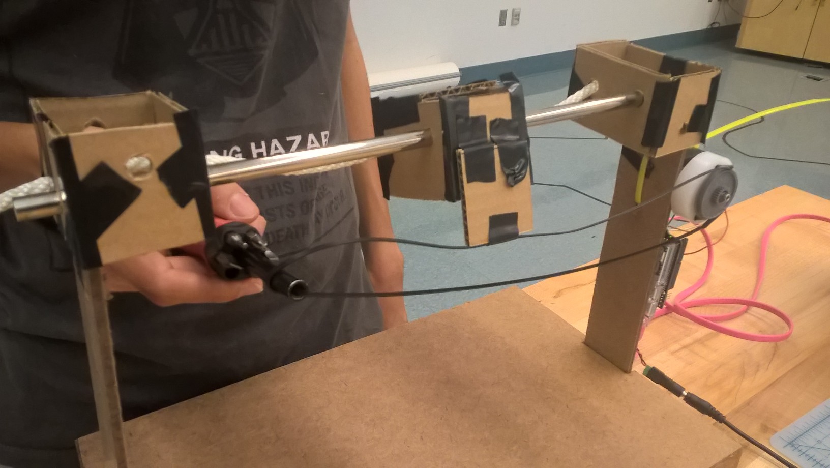 The first gantry prototype was a one-axis gantry attached to a platform composed of a wooden panel and two wooden pieces salvaged from the general use stock bins. These were hot glued together to form a platform and side pieces. Team members then put two cardboard boxes with holes in them on top of this frame to hold the rods up. The dispenser was attached to a third cardboard box with two holes in its side, one that slid the system along the axis and another that slid along a nylon rope that stabilized the system, substituting for a second rod, which caused some issues with friction. This gantry also employed a gear, stepper motor, and belt salvaged from a printer we found at the Wellesley Recycling and Disposal Facility and a short metal rod resting on an attachment piece from the metal bin in the general use stock bin. The gear, which we shielded using pieces of poster paper, moved the belt, which attached to the dispenser moving along the rods and then fed over the metal piece. The arduino attached to the side of this system and controlled the stepper motor’s movement. This system did not work particularly well: the nylon rope caused jamming along the gantry and the belt was often loose, so we often had to weigh it down to tension it. Furthermore, this was only a one-axis gantry and didn’t even approach the desired complexity for the prototype.
The dispenser was essentially a solid tube with a hole in it and a slight lip that could hold sprinkles. It was originally designed to be more of a funnel with a tube attached to it and a turning piece in the center, but time constraints made it so that the team focused mostly on the gantry, leaving the complex parts of the dispenser behind.
Prototype 2
 The new gantry included laser cut pieces, linear bearings, and a second rod salvaged from a laser cutter. The plastic gear from the earlier iteration was replaced with a pulley from the same laser cutter and the salvaged metal piece was replaced with an actual machined part. The laser cut pieces replaced the cardboard pieces, and the linear bearings fit into the holes in the center piece that moved along the rods to help the friction problem. The Arduino was still attached to the side. The band sawed build plate from the last prototype was replaced with a cardboard platform used to test the functioning of the dispenser. While the team had an idea about how to tackle a 2-axis gantry from this prototype, the gantry was still one axis and despite the addition of rods and linear bearings, there were still some problems with friction. Similarly, the belt’s tensioning issues did not disappear with the addition of gears. The team resolved to replace some of the scavenged parts for better fitting ones and to focus most of the energy for the next sprint on creating a working 2-axis gantry.
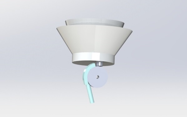
Liv, who was responsible for the dispenser at the time, added a layer of complexity to the dispenser by 3D printing a smaller version of the full funnel, which included a conical component, base with a hole to attach to the turning part and a hole for the sprinkles to go through. The hole for the sprinkles extended down into a tube that hovered above a conveyor belt which had some guiding walls on top that were made of small lines of paper forming a triangular shape with an opening at the belt’s end. The team salvaged this conveyor belt from a 3D printer that spanned over two gears that Liv 3D printed. These gears spun on a small frame that connected to the main funnel. The idea was that the tube, which would spin with the help of a small servo motor, would support the motor. Its pac-man shaped base would push sprinkles through the hole into the tube and then onto the conveyor belt, which would theoretically push the sprinkles through the walls and off the belt. The hope was that the walls would make sure the sprinkle ended up in the desired position. This sort of worked: sprinkles would flood onto the conveyor belt when there were no jamming issues with the funnel and revolving piece, but then either the sprinkles wouldn’t move, would bounce in different directions, or would scatter once they hit the target, which we had set up to be a piece of tape. This dispenser left much to be desired in terms of accuracy and reliability, so the team “killed its darling” and began to consider other ideas that might be more consistent.
Prototype 3
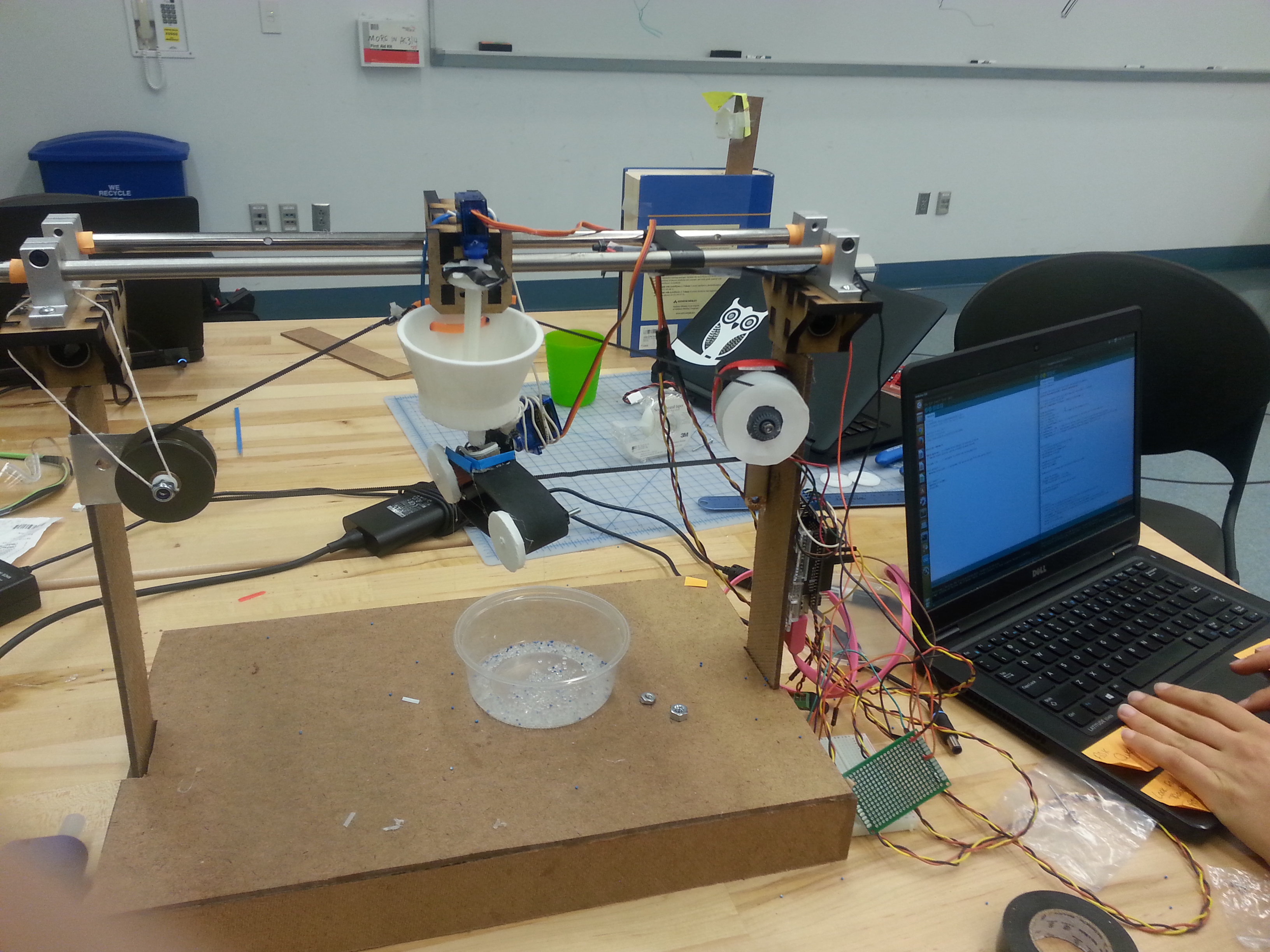
 The first half of sprint 3 involved massive changes to both the gantry and the dispenser. Justin CADed a gantry system that was entirely laser cut and other team members helped him assemble it. This gantry system had two axes, each of which comprised two parallel rods with bearings on them. . The x-direction rods were new and fit the linear bearings on that side perfectly, which reduced friction and any troubles that might come with jamming. The design for the boxes was replaced with side pieces that held up the gears and rod themselves. The design included small comb-like pieces that held up the platform and would allow users to adjust its height by fitting the platform between higher or lower teeth. Stepper motors were attached to the main frame using zip ties. The dispenser was attached in the middle of the belt on the left-right axis. While this gantry wobbled slightly and had some trouble with belt function, it performed the basic function that a two axis gantry should so was deemed a success by our team.
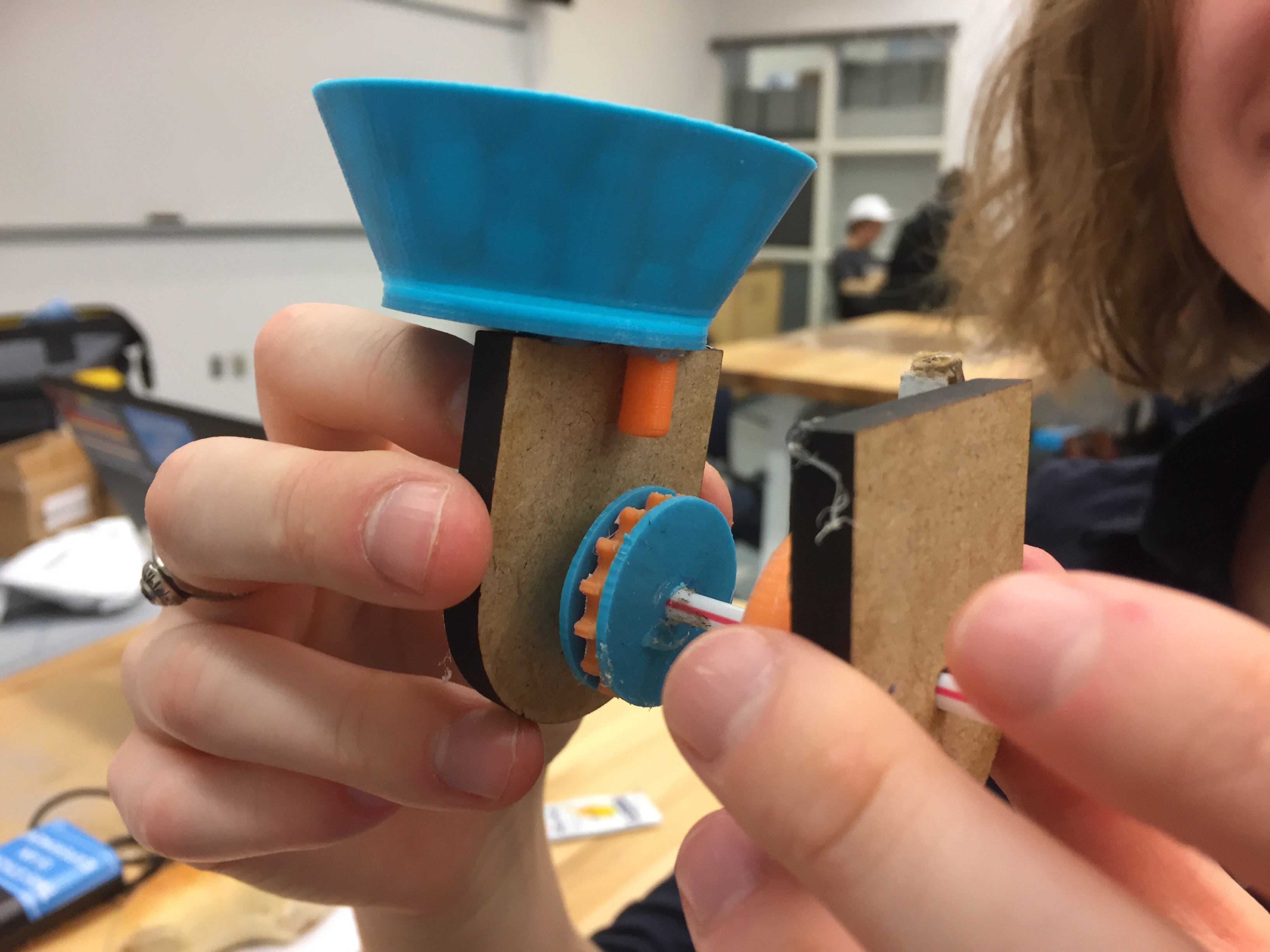
 Liv and Lydia took joint control of the dispenser for this sprint and tried an entirely new dispenser design in which the tube from the hopper dropped sprinkles into a gear covered almost everywhere but the place where sprinkles enter from the hopper tube. This gear was attached to a small servo motor that turned it so that it could dump into a tube positioned flush against the gear’s side. The entire gear system was attached to the hopper by the covers on the gear’s sides, which extended upwards and were hot glued onto the bottom of the hopper. The tube flush against the gear later had a funnel attached to its bottom because the sprinkles sprayed somewhat when they came out of the end of the tube. Ultimately, this edition of the dispenser showed promise, but demonstrated significant jamming problems that later had to be addressed by simplifying the dispenser system.
Prototype 4
 Later in sprint 3 a different prototype for the gantry emerged. Justin re-CADed the gantry to include small platforms that held up the stepper motors and supports. The rest of the team helped him machine and assemble this gantry. The pieces turned out thinner than expected, so required hot glue to connect, but still formed a stable frame. New belts were purchased and fitted, which helped reduce problems with tensioning and the belt’s interaction with the gear. Limit switches were also added. The new gantry, once integrated with functioning arduino code, made the gantry perform almost perfectly. The only problem was some minor jamming along the forward-backward axis.
Prototype 5
The final gantry is a tweaked version of the previous gantry. The laser cut frame is the same, as are the gears and belts. A zip tie was used to close one of the belts to create more tension and fix some jamming issues. Most of the focus this sprint went to the dispenser, as it was the final component needed to make the MVP function.
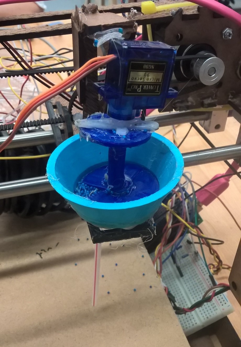
This final sprint began with an ideation and sketch modeling session in which the team decided to try a dispenser design based on an M&M dispenser Ariana used to own. The design involved a cylinder with a small cupped portion to hold an individual M&M that was rotated by a small servo. A tube on the dispenser collected M&Ms that would drop onto the cake or other sticky surface. A rigid tube above the dispenser’s tube arranged M&Ms into a vertical column to avoid jamming problems in the dispenser. The M&Ms were dropped from the dispenser into yet another tube that extended down towards the surface of the cake or other surface. After several reprints and filing, this dispenser system worked.
