How To Do It Yourself :
 Obtain the materials listed below.
- Download the full CAD from GrabCAD.
- Laser cut the part files found in "_to_cut_.zip". For our project, we used the Epilog Helix Laser Cutter. Most of these parts can also be cut by hand, although more labor may be needed to achieve the same quality.
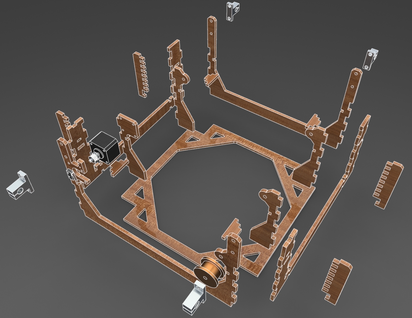
- Assemble the frame of the gantry based on the CAD and included drawings.
- Put the build plate on a level uniform across the four comb structures.
- Assemble the hard board pieces associated with the left and right gantry subasemblies. Put linear bearings in the large holes on the outsides of these structures.
- Cut your 3 ft rods in half, creating four 1.5 ft rods.
- Assemble the rods and rail guide supports such that gantry pieces each hang on a rod between two towers of the base. Tighten the rail guide supports.
 Use the long, diagonal "cross strut" piece to connect thetwo halves of the gantry.
- Assemble the center of the gantry and insert linear bearings.
- Assemble the two remaining rods such that the central gantry piece is suspended betneath the cross strut.
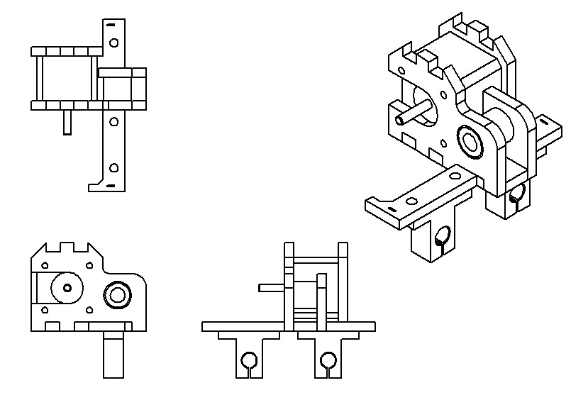
- Put pulleys onto each of the steppers (they fit into the stepper-motor-shaped holes in the gantry) and loop timing belt between the timing pulleys and corresponding free-spinning pulleys. You'll need to measure out the correct belt lengths. Fasten the ends of the belts to the moving gantry pieces.
- 3D print the dispenser and file as needed. Carefully hot-glue the top tube to the tube-shaped part of the dispenser. Then fit the bottom of the dispenser piece onto the bottom tube. Place the square-shaped attachment piece along the center part of the hardboard on the lef-right axis. Glue this piece down as needed. Attach the mini servo to the small bead-shaped attachment poking out to the left side.
- Secure the belts along the pulleys and gears by cutting them and attaching them around these components and to small slots on the end of the corresponding hardboard pieces. Small zipties are very useful in case the holes are too big or the belt is long enough to fit through both holes and meet in the middle.
- Re-create the electrical systems as demonstrated by the electrical diagrams. Attach the limit switches on the front-right side of the forward-back axis and on the side of the center hardboard piece of the left-right axis facing the axis with the other limit switch on it.
- Set up the arduino and download the code.
Materials
Much of what was purchased for this project was only used for prototyping. If you are interested in seeing how our money was spent, please refer to our offical budget. If, instead, you only care about materials necessary to reproduce this machine, see below.
| Qty. | Item | Unit Price | Subtotal |
|---|---|---|---|
| 1 | Arduino Uno | 19.99 | 19.99 |
| 1 | Adafruit motor shield | 19.95 | 19.95 |
| 2 | NEMA 17 bipolar stepper motor | 11.99 | 23.98 |
| 1 | Micro servo | 3.29 | 3.29 |
| 2 | Limit switch | 0.42 | 8.40* |
| 1 | Mini breadboard | 1.83 | 1.83 |
| 1 | Protoboard | 0.33 | 0.33 |
| 10 | Jumper wires | 0.07 | 0.72 |
| 25 | Wire - 22AWG (per ft) | 0.12 | 3.00 |
| 10 | Crimp pins and housing connectors | 0.06 | 0.62 |
| 2 | GT2 Timing pulley - 20T | 5.50 | 11.00 |
| 5 | GT2 Timing belt (per ft) | 2.50 | 12.50 |
| 2 | Free-spinning pulley | 5.00† | 10.00 |
| 4 | Linear bearing - 10mm | 2.95 | 11.80 |
| 8 | Linear rail shaft guide/support - 10mm | 2.49 | 19.92 |
| 2 | Aluminum rod - 10mm × 3ft | 24.52 | 49.04 |
| 10 | MDF sheet - .25" (per ft²) | 3.06† | 30.64 |
| 157.25 | PLA filament (per g) | 0.09† | 14.15 |
| 16 | ¼-20×.75" Bolt | 0.03† | 0.48 |
| 16 | ¼-20 Lock nut | 0.03† | 0.48 |
| 157.25 | Hot glue stick | 0.30† | 1.80 |
| 1 | Bag of M&Ms | 3.49 | 3.49 |
| 243.92 | |||
* Sold in bulk
† Estimate; exact price unknown