Electrical and Software
All of our source code is documented in our Github Repository.
The main goal of the electrical and software systems was to direct the mechanical components to drop the M&Ms in the right place. The software and electrical has had a few main challenges: transmitting data, ensuring in-bound commands, and integrating motor and image components. And, even though the team pivoted from placing tiny sprinkles to placing larger M&Ms, our overall vision for the software and electrical architecture stayed the same.
Throughout this project, the electrical and software subteam decided to prioritize the movement code throughout the first to third sprint. As we finalized our gantry design, the software subteam coded and connected the Image Processing component to the movement component via a serial communication stream, which was integrated in the third sprint. This approach has been less structured than the mechanical team’s approach because continuing progress often depended on each mechanical iteration. After careful planning and continuous integration and emphasis on the moving components, however, this subteam has been able to adapt and test components effectively to move the team forward. Here is how we planned our system:
Electrical And Software Components
Movements - Arduino C
Electrical
This system utilizes multiple components that control the mechanical system. These components can be summarized with:
Software
Designing this system was definitely the most challenging task for our software and electrical subteam, because the reliability of our motors and servos were not guaranteed. This system happens to be our most complex due to the number of components for which it needs to account. One of the biggest challenges to programming the movement was creating code that would be flexible as we added complexity to the gantry. To accomplish this, we decided to code separate functions for each action so that we can test different components separately and efficiently. As we worked on the code, we created the complementary electrical system to ensure that the software worked.
StepperControl.ino: We chose to use an Adafruit Motor Shield to connect our steppers to the Arduino Uno in part because the accompanying Arduino library simplified controlling steppers down to a few simple commands. Again, for simplicity, we also used the Arduino Servo library. The calibrate function runs the motor backwards so that the dispenser system moves towards a limit switch. The limit switch being pressed indicates that the motor should stop in order to not damage itself or the gantry. The motor then runs forward 100 steps to position the dispenser above the build plate. We keep track of the motor position in the code by updating stepperPositionX and stepperPositionY after each command is sent to the motor. This tracking of position only occurs after calibration has completed. The position the gantry is in immediately after calibration is the origin of the image. The commands sent over serial are processed into motor movement in the moveMotor function. This function takes a stepper motor, a number of steps the motor is instructed to take (this can be a positive or negative integer), the current position of the motor, and the minimum and maximum coordinates that the motor can take on as its arguments. The function determines whether or not the motor can move within the bounds of it minimum and maximum coordinates and then moves the motor accordingly. After the motor has moved, the function returns the new stepper positon. It is important that we protect the motors and gantry against damage by specifying the limits of movement, especially as we were in the early stages of sending commands over serial which often went out of bounds. These limits were experimentally determined. The motor runs backwards or forwards depending on the sign of the command. The servo motor is turned back and forth each time after the motors have moved the gantry because we only move the gantry when we want to drop an M&M. The stepper and servo movement are incorporated into the loop function. The code inside the loop only runs when there are instructions waiting in the serial input buffer. The instructions come in packets of 4 bytes in the form: direction of stepperX, displacement stepperX, direction of stepperY, displacement stepperY. Because of this, there needs to be 4 bytes in the serial input buffer before the movement functions can be executed. This ensures that we do not recieve any strange characters that we cannot process. The displacements that are read from serial as characters (in order to only read one byte at a time from serial) and cast to integers before being scaled by a factor of 75 to accomodate the size of the M&Ms and given a sign depending on the direction (0 is BACKWARDS, 1 is FORWARDS). The number of steps the yStepper is commanded to take is scaled again by 2 because the step size of stepperY is half that of xStepper.
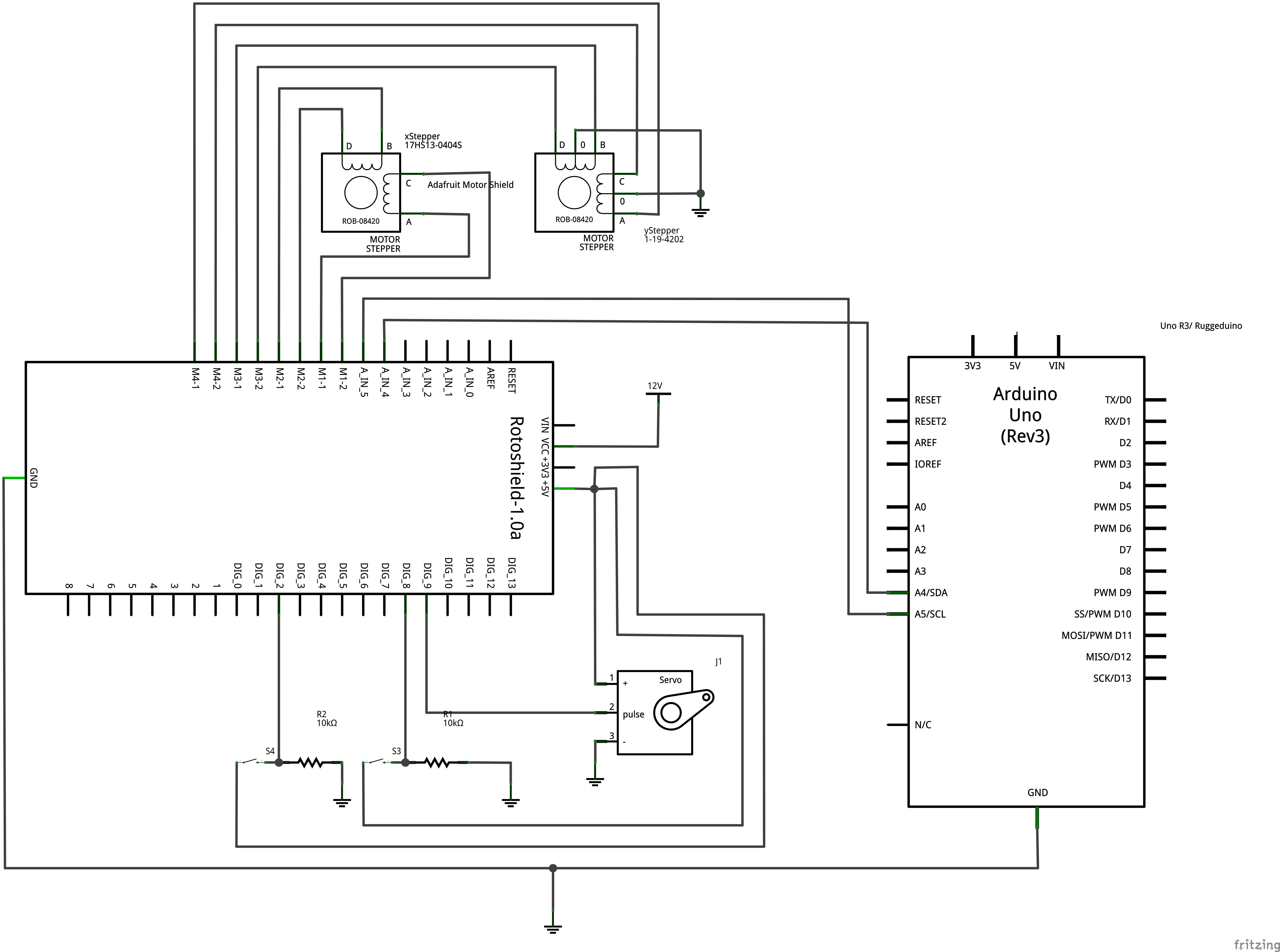
Image Processing - Python
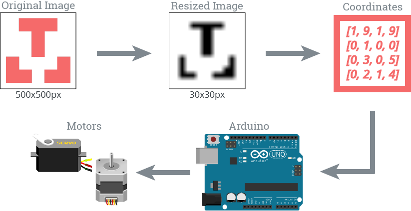
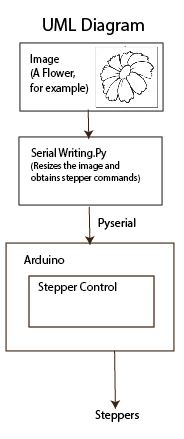
serialWriting.py: The Image Processing differs from the movement portion in that it cannot be summarized in terms of components. It actually depends on a specific sequence of steps:
- Given an image saved to the testimages directory, convert that image to a 10 pixel by 10 pixel, black and white image that is represented by an array of 0 (black) and 255 (white) values
- Loop through the rows and columns of array to obtain the coordinates of the black areas of the image. Each black point in the array has an x-component and a y-component, so we append the x components to a x-coordinate list, and append the y components to a y-coordinate list. This part is essential because it contains all the information we need to calculate the sequence of gantry commands.
- To calculate the sequence of gantry commands, we visit each element in the x-coordinate and y-coordinate lists to find the displacements between adjacent elements in the list. We need to save the displacement for each adjacent pair of coordinates because the gantry needs the displacement in each stepper motor to determine the right steps to travel. For example, if we want to get from the point (1, 1) to (3, 0), we need the x-direction stepper motor to travel 2 units, while the y-direction stepper motor needs to travel -1 units.
- After getting the list of displacements, we need to arrange the commands in a way that can be transmitted through serial. Because negative numbers cannot be transmitted easily, we formatted our displacement list in a peculiar way:
bytearray>[ 0 or 1, displacement in X direction, 0 or 1, displacement in Y direction>] The 0 represents a negative sign that helps the gantry decide whether to go forward or backward. This format makes sense because all the values in this bytearray can be transmitted through the serial stream.
Serial Communication - Combining Everything Together
 Last but not least, the electrical and software subteam had to combine these components to make a pictorial output. We thought a lot about our system of communicating via serial during this project. During the first weeks, before the image processing code was ready to be completely integrated, we primarily wrote motor commands by typing them directly into Arduno’s serial monitor. The commands came in the form of a positive or negative integer, representing the number of steps and direction the motor had to turn, followed by a character representing a color of sprinkle. This was a good first pass system for testing purposes, but as we started to integrate the python script into our system, we realized the importance of creating a more robust communications protocol. We settled on sending bytes over serial to represent direction and number of steps.
This system has limitations in that an 8 bit number only has 256 possible values that it can take on, as well as the fact that this new system did not leave room for specifying a color. However, after pivoting away from sprinkles to M&Ms, we found that our gantry was too small to ever need to move close to or above 255 steps at a time and that we would not be implementing multiple colors in the time that we had left to complete the project. Because some of the software subteam had experience with reading Arduino’s Serial Monitor output from a Python script, but not in reverse, trying to read Python’s output from Arduino’s Serial Monitor was a fun challenge. Thankfully, the software subteam was able to solve this challenge by converting inputs to bytearrays and convert incoming readings on the Arduino side into characters.
Software Dependencies
- Arduino IDE or equivalent (download here)
- Adafruit Motor Shield V2 for Arduino (download here)
- Servo library for Arduino (included with Arduino IDE, overview of library here}
- Numpy (download information and documentation here)
- Open CV (download information and documentation here)
- Pyserial (download information and documentation here)
- Matplotlib (download information and documentation here)
All of our source code is documented in our Github Repository.