Mechanical Overview
Gearing, mirrors and structure
Pan-Tilt Mechanism
We designed the pan-tilt mechanism, the most important mechanical subsystem, with a mind for the
laser and the necessary range of motion. The pan actuator has a two to one gear ratio because the laser
needed to be able to rotate 360 degrees to reach all angles of the sphere.
 We initially considered some combination of standard 180 degree rotation servos, but we decided that it
was considerably easier to change the gear ratio.
We initially considered some combination of standard 180 degree rotation servos, but we decided that it
was considerably easier to change the gear ratio.
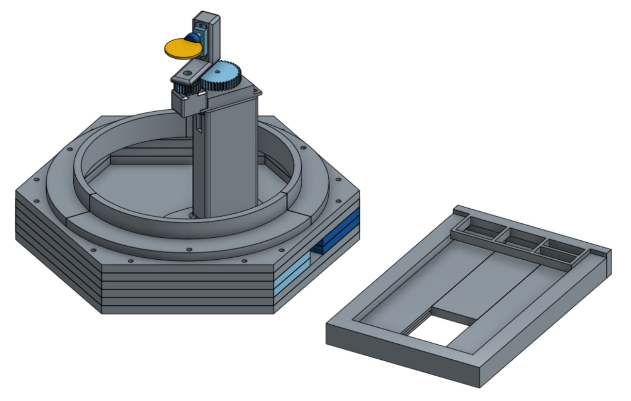
Early on, we assumed the laser diode would be small, low mass, and easily mountable on a pan-tilt. However, the first laser we used did not have the required frequency to activate the phosphorescent paint. We replaced this with a more powerful laser in the blue-violet range, but the new laser is too large to be mountable. To solve this we designed a pan-tilt with a stationary laser and a mirror that rotates to change the direction of the beam. We also found through iteration that we needed to mount the laser closer to the pan-tilt mechanism so it would hit the center of the mirror more consistently. We solved this by designing a separate mount for the pan-tilt and laser together that rests on top of PVC pipe, which mounts to the base. With this setup, the mirror is at the exact center of the sphere, simplifying the software pipeline.
Full CAD of the mechanical system
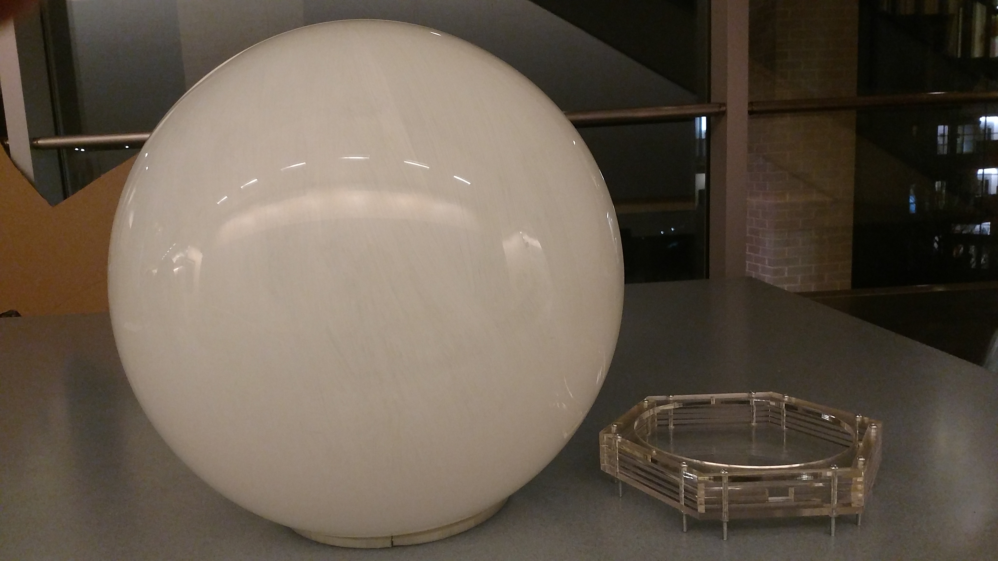
Base
Another critical mechanical subsystem, the base for the spherical display, is designed to fulfill a few key requirements. The base needs to provide a framework for integration of the other mechanical and electrical components, in addition to serving as the infrastructure for a power coupling failsafe. To this end, we prioritized a mechanism that would lock into place easily and provide a consistent electrical connection. Early on, we considered a support track for the collar of the sphere with holes for conductive pegs that would complete the laser circuit. This design’s primary strength was that it would lock into place without an over complicated locking mechanism. As shown in the diagram, this base was planned in two layers for easy electrical implementation, with the laser mounted in the bottom layer.
As we fleshed out the rest of the project, we discovered issues with the base that necessitated a redesign.
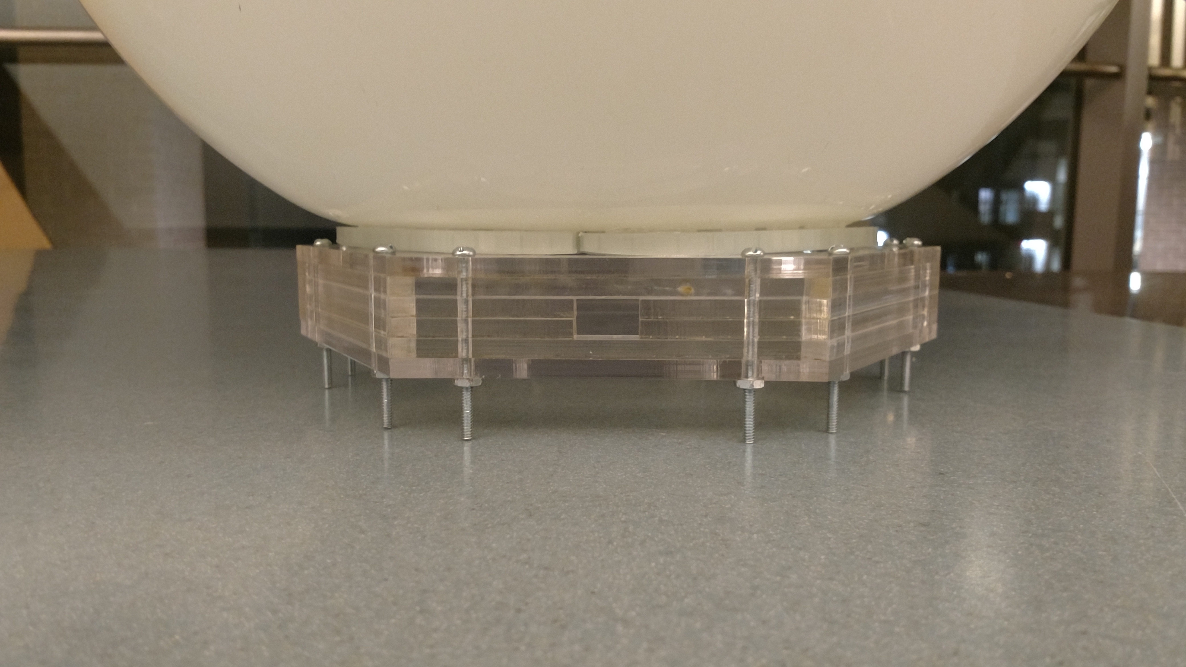 In putting together our first pass, we realized that there was not enough space in the sphere for the
controls hardware. To account for these issues, we built space into the base for the controls subsystem. We
also further simplified the fail-safe by replacing the conductive pegs with copper tape that covered the entire
bottom side of the collar. With this change, placing the sphere would consistently power the laser, but there
was no locking mechanism. To compensate for this change, the final version includes a basic dowel pin locking
mechanism that holds the sphere in place. The base is 4.4 cm tall and has a hollow 2.5 cm tall space in the
middle, enough for two Arduinos and a Raspberry Pi.
In putting together our first pass, we realized that there was not enough space in the sphere for the
controls hardware. To account for these issues, we built space into the base for the controls subsystem. We
also further simplified the fail-safe by replacing the conductive pegs with copper tape that covered the entire
bottom side of the collar. With this change, placing the sphere would consistently power the laser, but there
was no locking mechanism. To compensate for this change, the final version includes a basic dowel pin locking
mechanism that holds the sphere in place. The base is 4.4 cm tall and has a hollow 2.5 cm tall space in the
middle, enough for two Arduinos and a Raspberry Pi.