Electrical Overview
Power, touchscreen and microcontrollers
The electrical system is made up of two important subsystems: the laser fail safe and the microcontroller support infrastructure.
Safety
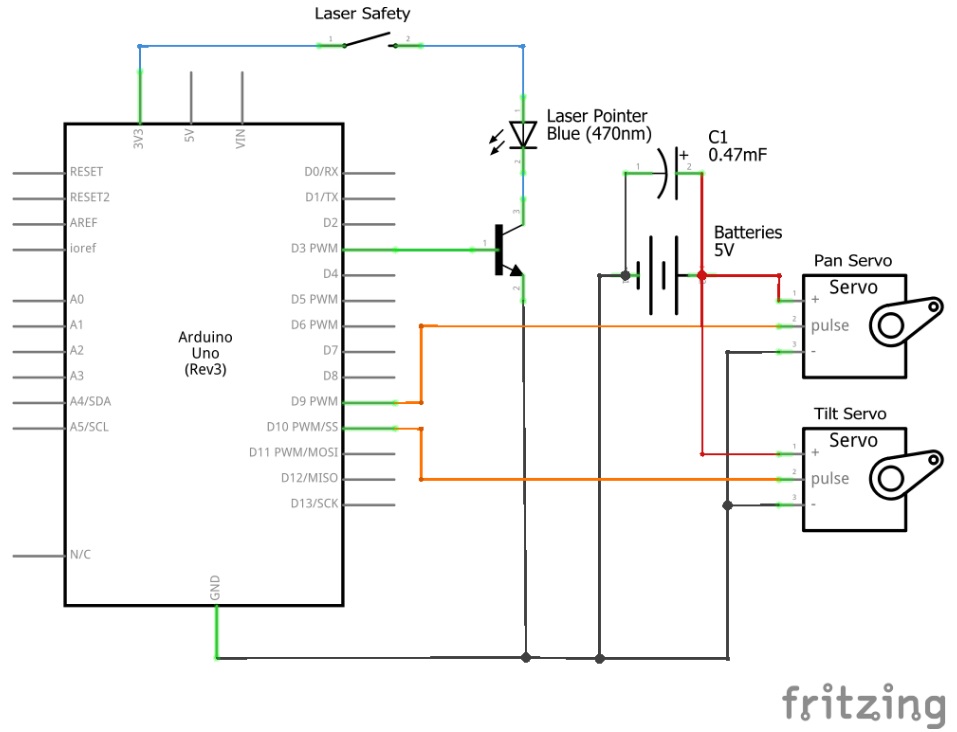
The fail safe for the laser is an integral part of the electrical subsystem considering the power of the laser used. The laser we are using, a class IIIa laser, is capable of causing permanent eye damage in 1/100th of a second. To ensure the safety of the user, we needed to make sure the laser was only powered when it was completely obstructed in every direction by the spherical display. To do this, we designed a basic fail safe that used the sphere to complete a circuit powering the laser. When the sphere is on the base, copper tape around the rim of the sphere connects to copper tape pads on the base. Ground and power from the laser are soldered to the two pads, so the laser only works when the sphere is down.
Laser Control
Our laser requires 3.3V to function properly (usually supplied by two AAA batteries). To more fully integrate it into our project, we decided to power it from our Arduino. Since we wanted to be able to control whether the laser was on or off as well as power it from the Arduino, that required us to use a transistor to switch the 3.3V power to the laser on and off via the 5V from one of the Arduino’s digital pins.
Servos
The most problematic aspect of our electrical system are the two servos that actuate our pan-tilt mechanism. On their own, the servos are quite jittery—an issue caused by large power surges when the servos start to move. In either case, it reduces the accuracy of the servos’ movement as well as the quality of the final image drawn on the sphere. We resolved this issue by putting a single large capacitor across the power line for the servos. Voltage is stored in the capacitor so that when a power surge forces the arduino to briefly shut down, it can quickly restart to prevent inconsistent motor controls.
Touchscreen
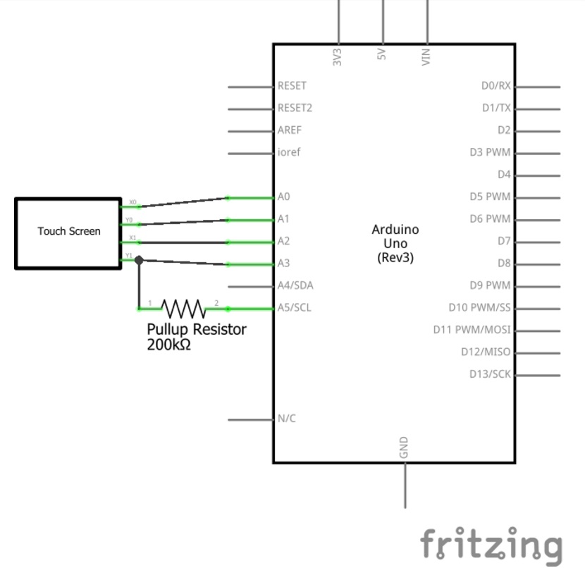
For user input, we have a four-wire resistive touchscreen. Such a touchscreen is composed of two thinly separated layers of plastic, each coated with Indium Tin Oxide (a transparent resistive material). Each layer has electrical rails along two of its opposite edges (the short edges on one layer, the long edges on the other), so that when a voltage is present on the rails of one layer, when the screen is pressed it passes a voltage to the other layer, which can be read as input from the other rails. We can alternate which rails are input and output rails to get pairs of XY coordinates on the touchscreen. We can also use a pullup resistor to test whether the screen is touched; when the output pin connected to the resistor is set to high, the corresponding input pin for the touch screen (Y1) reads high unless the touch screen is touched, completing the circuit when the X1 pin is set to ground, in which case Y1 reads low. See this PDF for more details on the circuits involved.
Data Processing Infrastructure
Our electrical system is, for programming and data transmission purposes, distributed between two Arduinos and a Raspberry Pi. User input is handled on by one Arduino, which communicates via serial over a USB connection to the Raspberry Pi, which, after processing the input, writes motor commands to our output-oriented Arduino (also via serial over USB).