
Sprint 3
Goals
Revised Goals
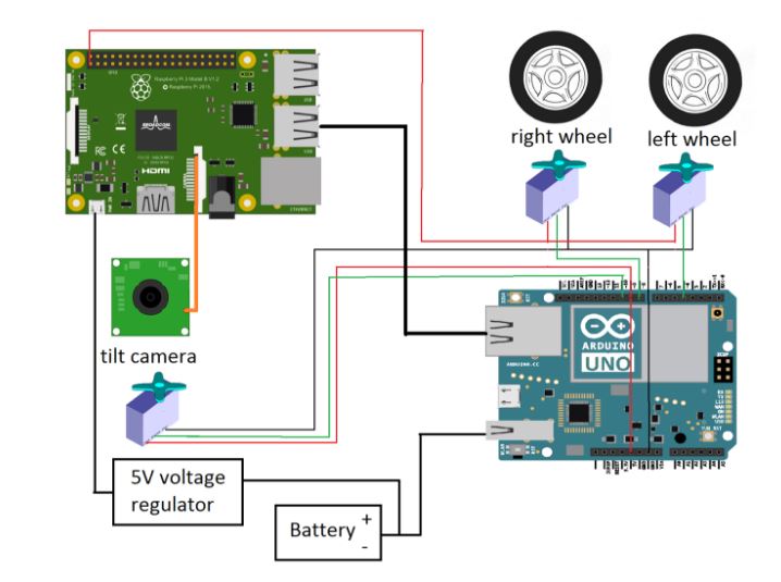
Integrated System Diagram
Goals
- Iterate and improve on mechanical design
- Decrease response time of face detection algorithm
- Finalize user interaction/experience
Revised Goals
- Iterate and improve on mechanical design
- Decrease processing time of face detection algorithm
- Fully integrate all components
- Finalize user interaction/experience
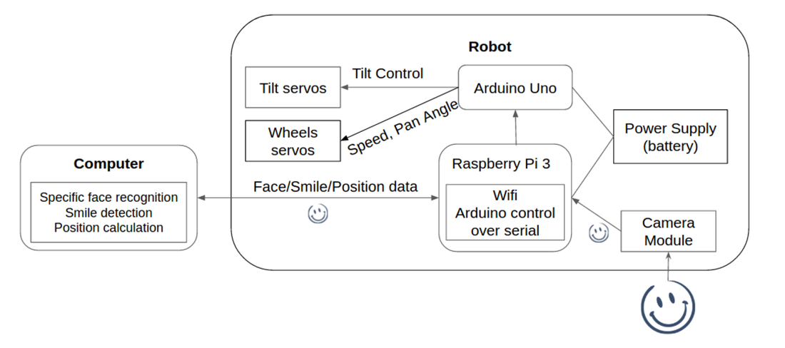
Integrated System Diagram
Working System Demo
Development
Software:
In this sprint, we mainly focus on streaming video from raspberry pi to computer by socket connection through wifi and control the tilt servo and wheel servos of the robot. Adding the computer to the system was done to cut down the runtime of the face detection algorithms.
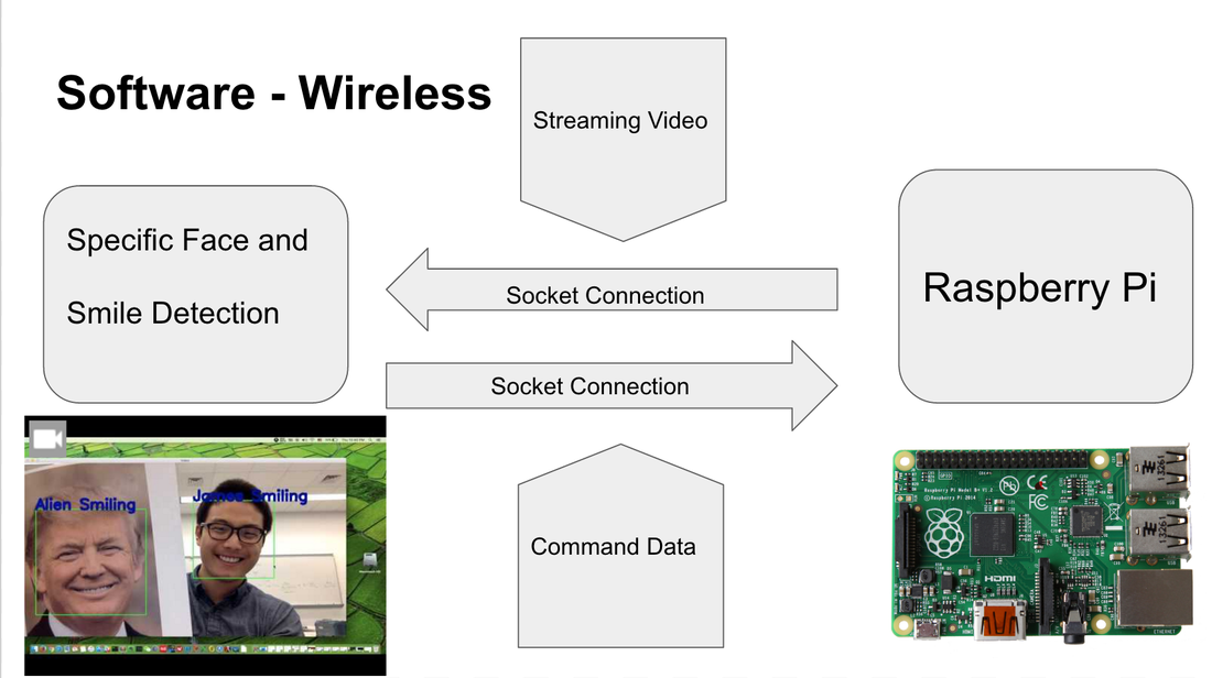
1. Wireless Communication
For fast speed streaming video, we choose to use TCP connection instead of UDP connection (https://pymotw.com/2/socket/tcp.html). There are also libraries like gstreamer which we also quite some time to experiment with but didn’t get them to work easily yet. So the computer will get video data from pi and respond with command data back. Below diagram shows how we used wifi to make the face recognition algorithm's runtime shorter.
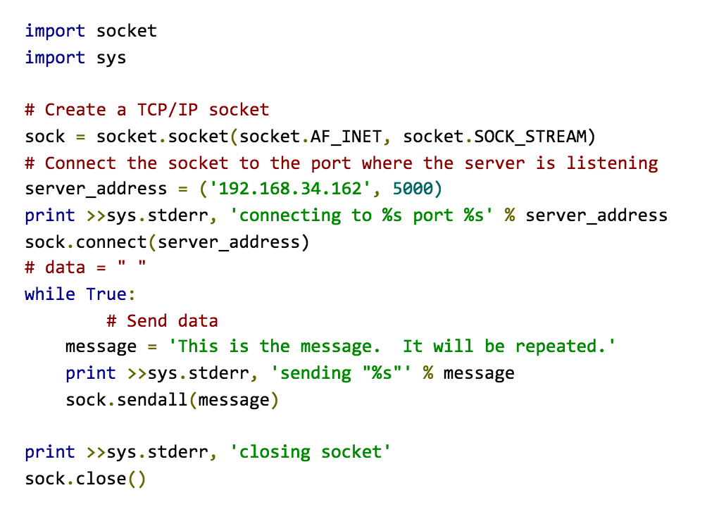
Eample code on the TCP client scoket connection
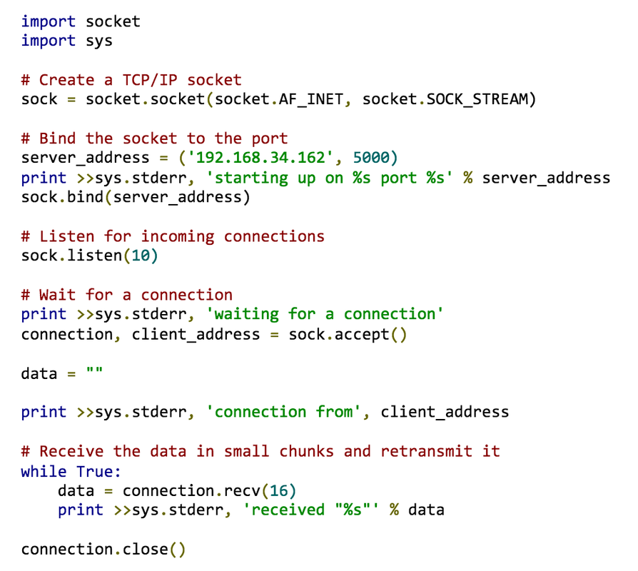
Eample code on the TCP server scoket connection
2. Control Codes for the Servos
For this sprint, we were successful with implementing both the tilt and the pan control codes.
a. Tilt Servo Control
For this sprint, we were successful with implementing both the tilt and the pan control codes.
a. Tilt Servo Control
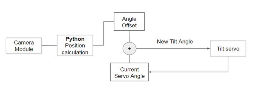
The above diagram shows how the tilt control code works. We first have our python code to calculate the tilt and pan angles, and the distance of the person from the camera. From the current tilt angle offset, what we do is we just add the angle to the current servo’s angle position, and write the new position to the tilt servo. Since the tilt servo just writes to specified angle, this simple control code works well. The actual code that controls the tilt servo is on the sprint 2 page.
b. Wheel Control
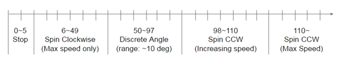
For the wheels, the servos we used were continuous rotation servos, which are different from the tilt servo in that they do not write directly to the angle we specify. Instead, they have different ranges where the servo rotates continuously clockwise, counterclockwise, and writes to discrete angles.
When we chose the set of servos that we were using, we thought we would be able to control its rotation speed both ways. However, we realized that the servo ran differently from what was specified in the documentation in that the speed control was only available one direction.
The following diagram shows the test result of the servo’s behavior when we used servo.write(angle) to control the servo.
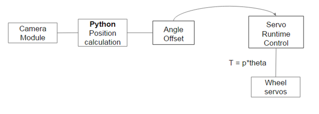
With this servo characteristic, we weren’t able to do speed control, since it provided only single speed in clockwise rotation. As an alternative, we instead controlled the servo runtime, turning it on for only certain amount of time, using time.sleep() functionality. From the angle offset, we multiplied the offset to a proportional constant and made the program stop longer, so that if the offset is big, then the servo would run for longer period.
The following diagram shows how the wheel control work.
The following diagram shows how the wheel control work.
Below is the code that we wrote for the wheel control, integrated with our code.
Mechanical System:
Sprint 3 was an improved version of sprint 2. The chassis was redesigned to house the raspberry pi in the cover, and all the inner dimensions were adjusted to accommodate the inaccuracy of the 3D printers and real world measurements. Also, the head was redesigned so that the head followed with the camera to provide a better user experience. The wheels were changed to Trippex generic wheels.
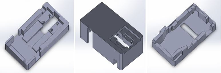
The Chassis Individual Parts: The base, the bottom of the base, the cover
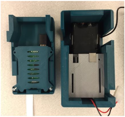
Battery and UNO fits in the body and the Pi fits in the cover
The chassis was lengthened from the Sprint 2 version so that there could be more space for the wires. The base dimensions were adjusted to fit the servos, the battery and the UNO nicely. Also, the bottom of the base was carved out more to ensure that the trailing wheel was levelled evenly with the wheels, and that the trailing wheel was able to rotate around freely without getting stuck. The cover was designed to house the Raspberry Pi case. Such that the base of the case will be levelled with the cover when it is inside the cover. Also, the rectangular hole was carved out at the top and on the side for the raspberry pi connector and power supply connector respectively.
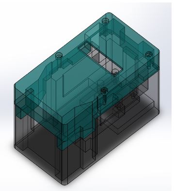
Chassis Assembly
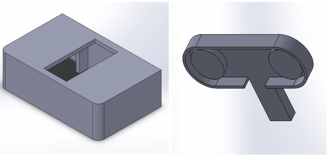
The Head Individual Parts: Head holder (tilt servo mount), Head (camera mount)
The servo was mounted inside the head holder and the pi camera module was attached to the head which was connected to the tilt servo in the head holder.
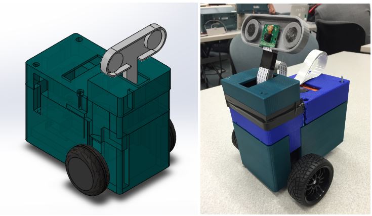
Sprint 3 Mechanical Design Assembly, Printed and Assembled Sprint 2 Mechanical System
Electrical System:
The main improvement to the electrical system for sprint 3 was to remove the external power supply and have the entire system powered by a rechargeable battery. We did this by including a simple switch-mode 5V voltage regulator board, Hobbywing 5V 3A Switch-mode UBEC, to provide a steady 5 volts for the raspberry PI and all of the servos. Since the Arduino Uno has a built in voltage regulator, we provided the battery voltage directly to the voltage input of the arduino. Our battery selection process was that we wanted a battery in the 7 - 12 volts range (since that is the advised input voltage range for the arduino). We also wanted reasonable battery life, at least an hour of full power operation, or at least 1 amp-hour. Lastly, we wanted to use a nickel metal hydride (NiMH) battery over lithium based batteries for simplicity of charging and because unlike lithium batteries, NiMH batteries are not as sensitive to over-discharge. Based on this criteria, we selected the Tenergy 2000 mAh 9.6 volt rechargeable battery pack as the ideal option.
Lesson Learned
Iterative prototyping reduces uncertainty
Team communication and health is crucial
Risk Identification for Final Sprint
Iterative prototyping reduces uncertainty
- Always have a backup plan in case parts might not work the way they should
- Limited speed control over wheel servos
- Initial wheels we got were not fixed
Team communication and health is crucial
- Assigned two or more members to each task
- Set deadline at the start of the sprint
Risk Identification for Final Sprint
- Data Parsing Problem
- Lag caused streaming video from pi and processing algorithm on computer could cause problems
- Changing to stepper motors will require mechanical/electrical system changes