Sprint 2
Goals
Revised Goals
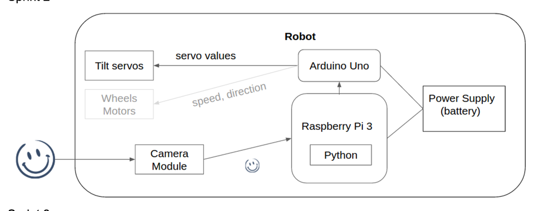
Integrated System Diagram
Goals
- Mount camera mechanism on vehicle
- Stream Videos from raspberry pi camera module using wifi
- Decide on the control system for the vehicle
Revised Goals
- Mount camera mechanism on vehicle
- Communication between Raspberry Pi and Arduino UNO
- Smile Detection and specific face detection
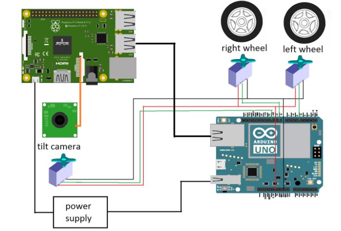
Integrated System Diagram
Working System Demo
|
|
|
Development
Software:
In this sprint, we stream the video feed from raspberry pi’s camera and run general face detection algorithm on the pi instead of computer to directly control the arduino to control the tilt servo from pi. Meanwhile, we also implemented our own specific face detection algorithm and general smile detection algorithm by using machine learning method.
1. Raspberry Pi integration
a. Setting up Raspberry Pi
Installed: OS, Raspbian, software library, OpenCV2
b. Integration with PiCamera Module
For this sprint, we moved our python code to run separately on Raspberry pi, so that the robot is isolated on its own. We’ve already tested the Arduino code that controlled the tilt motor before with laptop camera, so all we had to do was to adapt our python code so that it can run from the camera module attached to the Raspberry pi.
Integrate picamera with openCV:
This code captures the frames from the picamera and uses the openCV’s image show function (imshow) to display them on screen. The only thing that is different from our previous code is that now we need to import the picamera library.
Integrate with faceTrack.py:
c. Serial communication between Raspberry Pi and Arduino
There was a huge problem with connecting the raspberry pi and the arduino uno over serial port and at the same time drive servos. For this sprint, we spent much time trying to debug the Arduino’s servo library to work along with the serial communication, but it was not solvable because of the Arduino’s hardware limitation. To briefly explain the problem, both the serial communication library and servo library use the same built-in Arduino timer, and having the serial communication blocks the Arduino from controlling the servo. (see: http://forum.arduino.cc/index.php?topic=82596.0 )
We were able to resolve this problem by using a python library called nanpy, which once uploaded to Arduino, Raspberry Pi controls the Arduino as a slave over the serial port. Nanpy allowed us to code arduino codes in python, and resolved the library conflict problem in Arduino. You can find the documentation for the python nanpy library here: https://pypi.python.org/pypi/nanpy
Here is an example python code that we used to control the servos using the nanpy library:
And this is how we integrated with our system:
2. Machine learning algorithm - Specific face / smile detection
In this sprint, we decided to implement our own specific face detection and general smile detection by using machine learning algorithms instead of importing and using some existing algorithms.
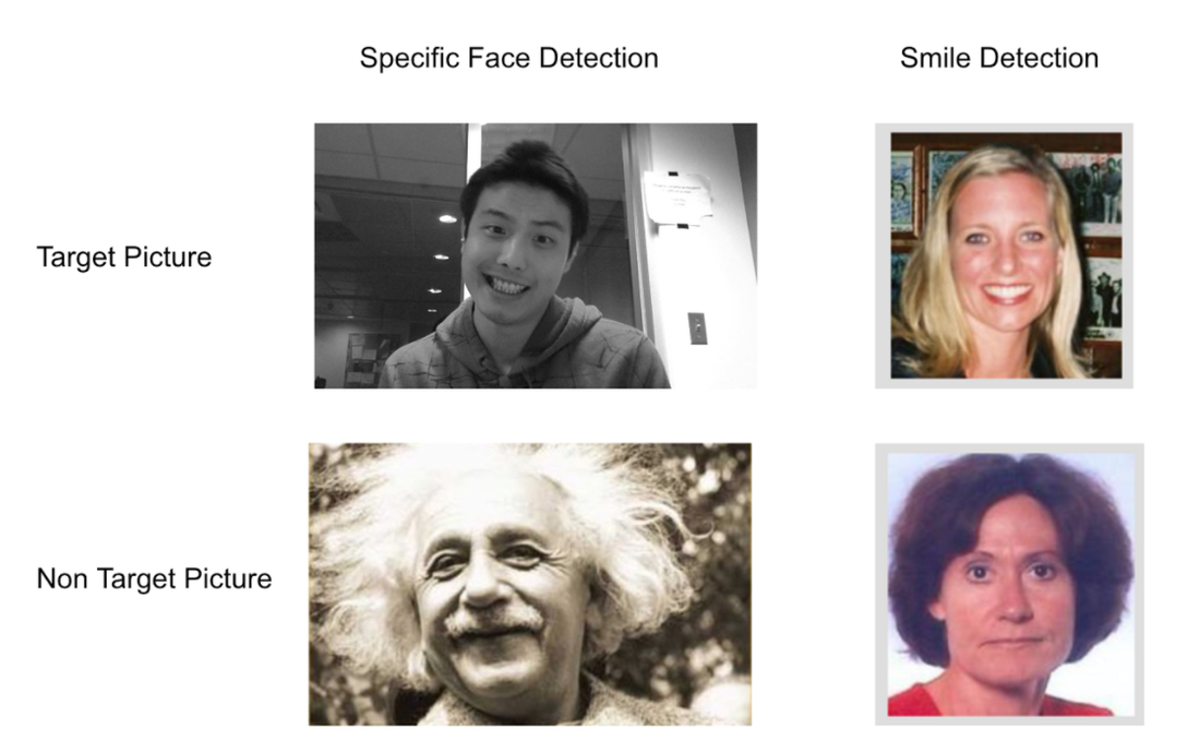
The specific face detection algorithm will output true or false based on if the specific face is in the frame or not. The general smile detection will output true or false based on if the general smile is in the frame or not. We plan to run both algorithms in parallel and generate 4 possible output based on the combination of the outputs from these two classifiers. From these 4 possible outputs, we could write conditions to program the robot to behave intelligently.
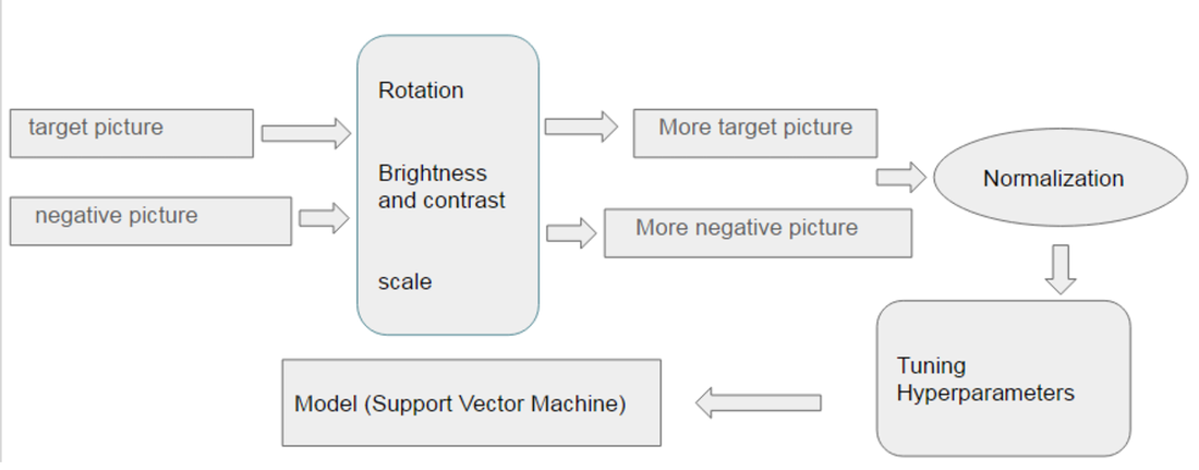
The following is the general routine of training both machine learning algorithms. We have positive data and negative data (images of faces) by using rotation, translation, scale, changing brightness and contrastness, we generate more general data to increase our data size to make the model more robust and general. We use support vector classifier machine learning (SVC) from scikit-learn library (http://scikit-learn.org/stable/modules/generated/sklearn.svm.SVC.html) which needs our data to be normalized (shifting mean of the data to 0 point and standard deviation). Due to the structure of the SVC, we also need to use an algorithm, grid search algorithm to tune the hyperparameters of the model (http://scikit-learn.org/stable/modules/grid_search.html).
Mechanical System:
For Sprint 2, we created a chassis to enable the facelook to move. The chassis was used to implement the pan mechanism, and a head was used to implement the tilt mechanism.
Chassis
The chassis was designed to house the Arduino UNO, Tenergy 9.6 V 2000 mAh NMH high capacity battery and two continuous rotation servos, the Tower Pro MG996R. Each servo was connected to Hobbypark Rubber Tail Wheel each. However, the wheels were freely rotating and we had to glue gun the wheels to hold them in place (we placed order for new wheels but they did not arrive on time for integration).
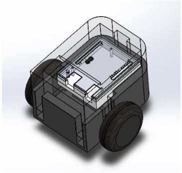
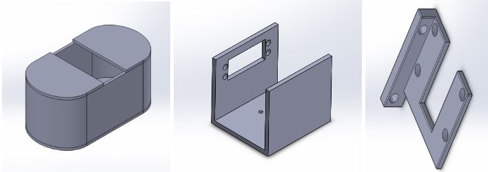
The chassis was designed as two separate components, a cover and a base, which fitted each other. The base was used to hold the servos, battery and the UNO Case, and for attaching the third trailing wheel. The rectangular hole in the cover was made to connect the UNO (inside the chassis) and the Pi (mounted on top of the chassis)
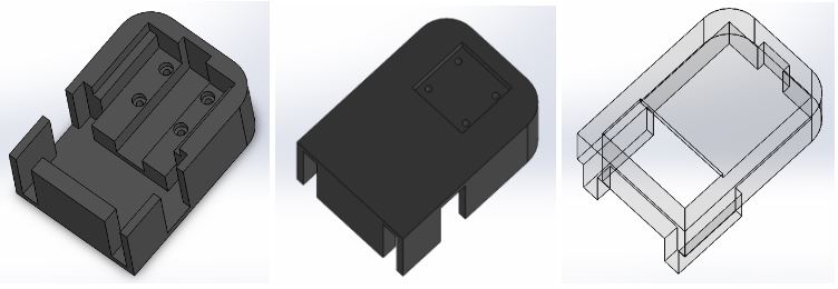
Individual Chassis Parts: Base, Bottom View of Base, Cover
The bottom layer of the base was designed to fit the servos perfectly. When the servos are in place, it levels with the next layer, which would fit the battery. The battery will level with the next layer, which fits the Arduino case. The trailing wheel was attached to the bottom of the base using 4 4-40 nuts and bolts.
Chassis Assembly
The fabrication specifications were slightly off because of inaccurate measurements and the 3D printer are not accurate and requires ~1mm to 2mm offset. The inside of the base had to be milled to accommodate the servos and the batteries. Also, the height of the trailing wheel was measured wrongly and the chassis was slightly tilted to the front. The pi was mounted on the top but we decided to house it inside the chassis for the next iteration.
Head
The head contained the raspberry pi camera module and the tilt servo. The tilt servo was switched to Spektrum A5040 Metal Gear Servo for high accuracy in tilt control.
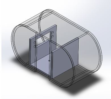
The head consisted of three parts: shroud, tilt servo holder and the camera mount. The same camera mount from Sprint 1 was used, which was attached to the servo mounted on the servo holder. These were housed in the shroud.
Individual Head Parts: Shroud, Tilt Servo holder, Camera holder
Head Assembly
While testing, we realised that the bolts used for holding the camera module came loose after repeated use. Therefore, we decided to discard the mounting method that required the use of nuts and bolts. Also, the head design which houses the tilt mechanism in the shroud makes it hard for the user to tell if the eye (camera) is following the user’s face. Therefore, we decided to change the head design so that the entire head was tilting with the camera for the next iteration.
Case
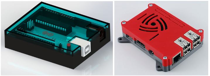
For UNO, we used a UNO case designed by Ryan Laird (https://grabcad.com/library/arduino-uno-case-3) and for Raspberry pi, we used a Pi case designed by 0110-M-P (http://www.thingiverse.com/thing:922740)
Cases: Arduino UNO case, Raspberry Pi 3 Case
Integration of Mechanical parts
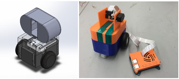
Sprint 2 Mechanical Design Assembly, Printed and Assembled Sprint 2 Mechanical System
The assembled parts does not include the shroud because it was hard to tell if the camera was tilting with the face if it was housed inside.
Electrical System:
For Sprint 2, we moved the facial recognition algorithm to raspberry pi 3 using the pi camera module for video capture. Our electrical system was again fairly simple, consisting of three servos: a servo for the tilt mechanism, and one servo for each of the two drive wheels. We decided to use a faster, more precise digital servo for the tilt mechanism instead of the inexpensive hobby servo. We wanted to find an affordable servo with as small a deadzone as possible and with the highest angular resolution. We decided to use the Spektrum A5040 digital aircraft servo as this was a good balance between performance and cost. For the drive wheel servos we used TowerPro MG996R continuous rotation servos. We used these because they advertised that they allowed for continuous controlled rotation in both directions and were very affordable. Our plan was to perform the pan function by turning the vehicle using differential speed control of the two motors. The servos were connected to and directly powered by the UNO. The PI and UNO were connected via USB connection. Power was supplied to the PI and UNO from an external power supply. The main problem we ran into with this system is that, contrary to the advertised specifications, the MG996R servos only had proportional speed control in one direction while the reverse direction was either full on or full off. This meant that we had to switch our control scheme to account for the inability to control the speed in one direction.
Lesson Learned
- Timebox and know when to get help so that we do not sink endless time into any one problem
- Be more aware of fabrication bottlenecks, especially the 3D printers
- Always have an alternative plan in case things do not work as expected the first time
- If a problem seems excessively complicated, we should be sure that we are not making the problem more complicated than it has to be - simpler is usually better.
Risk Identification for Sprint 3
- Raspberry Pi takes a significant amount of time to process video/images - this could be problematic as we move forward
- If we have to move to a more powerful microprocessor/single board computer, we will need to consider the time required to become familiar with a new system
- If we move towards wireless video streaming to a laptop for processing, we will have a new set of challenges such as latency.

