
Sprint 1
Goals
Deliverables
Integrated System Diagram
Goals
- Have a working software that detects face from webcam and sends distance, angle data to Arduino
- Have a working pan/tilt mechanism integrated with the software
Deliverables
- Working software that detects face from webcam and sends distance, angle data to Arduino with communication problem
- Working pan/tilt mechanism integrated with the software
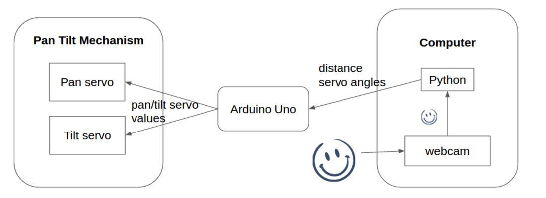
Integrated System Diagram
Working System Demo
Development
Software:
During this sprint, our objective was to run general facial recognition algorithm in real time and build a code that outputs the location data (pan angle, tilt angle, distance) of the recognized face relative to the webcam's position. We first used the laptop's built-in camera and the existing third face detection library from OpenCV.
1. Face Detection Algorithm
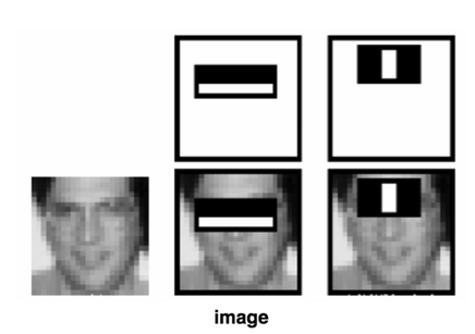
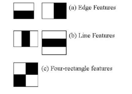
OpenCV is a common library that facilitates users to quickly prototype for computer vision task. We use Haar feature-based cascade classifiers as our general object detection algorithm for the first sprint. It uses multiple feature filters to extract features from images and use multiple stages of different window sizes to process the image. Figure below shows an example of how the Haar cascade classifiers work.
|
|
|
This algorithm is one of the Cascade of Classifiers. After extracting features from images, instead of applying all the features on a window, the algorithm group the features into different stages of classifiers and apply one-by-one (in a “cascaded” way). (Normally first few stages will contain very less number of features). If a window fails the first stage, discard it. We don't consider remaining features on it. If it passes, apply the second stage of features and continue the process. The window which passes all stages is a face region.
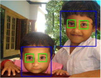
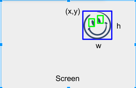
Below is an example code that implements the openCV's face recognition algorithm. It runs the algorithm, draws box around the face, and outputs the position of the top left corner (x,y) and the width and height of the box (w,h) in the format of list.
Below is an example code that implements the openCV's face recognition algorithm. It runs the algorithm, draws box around the face, and outputs the position of the top left corner (x,y) and the width and height of the box (w,h) in the format of list.
2. Location Calibration
The face detection algorithm outputs the positions and the width and height of the rectanglar bounding box that contains the recognized face in pixels. We need to use the data to calculate the relative distance of the face from where the webcam is positioned.
So how do we do that?
We were able to calculate the distance and relative angles using some geometry. Since what we see in the photo is just a smaller version of the reality, we can envoke triangle symmetry to calculate the distance, once we know the ratio between the actual size of the face and the size of the face on the photo for certain distance. Figure below shows the similar triangles with which we calculated the angles and the distances from.
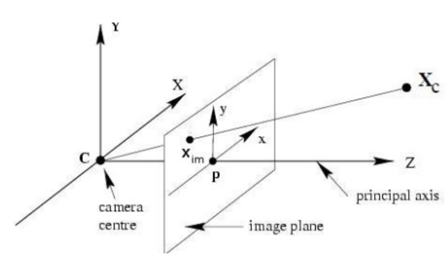
In this figure, Xc is where the actual face is located, Xim is the position of the face on the frame, and theta and phi angles are the angles which the line C-Xc is in with the principal axis on the XZ plane and the YZ plane respectively.
Below code uses the data output from the openCV and computes the distance (length of C-Xc) and the theta and phi angles. We've also encapsulated the whole code into class structure, so that it is more scalable.
Below code uses the data output from the openCV and computes the distance (length of C-Xc) and the theta and phi angles. We've also encapsulated the whole code into class structure, so that it is more scalable.
Code Editor
Mechanical System:
For Sprint 1, we implemented the pan and tilt mechanism using two H King HK15148 servos, which were readily available and good for rapid prototyping. Our mechanical design served as both pan and tilt mechanism and also as servo holders and Raspberry Pi camera holder. The dimensions were chosen so that the camera will be the center of axis of rotation for pan and tilt mechanism. This was done to make the software algorithm for calculating the distance and angle data simpler.
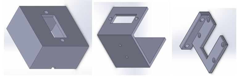
Individual CAD parts: Base (servo holder), Pan (servo holder), Tilt (camera holder)
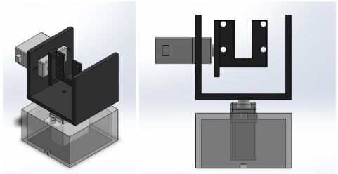
Pan and Tilt Assembly
Based on the dimensions of the servo and the Raspberry Pi camera module, relevant holes were made for the servo wires and to hold the servo and the pi camera in place using nuts and bolts.
We printed the design using makerbot 3D printers. The parts were assembled using 10 4-40 nuts, washers and bolts for the servos and 4 <2mm diameter sized nuts and bolts for holding the camera.
We printed the design using makerbot 3D printers. The parts were assembled using 10 4-40 nuts, washers and bolts for the servos and 4 <2mm diameter sized nuts and bolts for holding the camera.
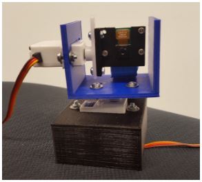
Printed and assembled pan and tilt mechanism
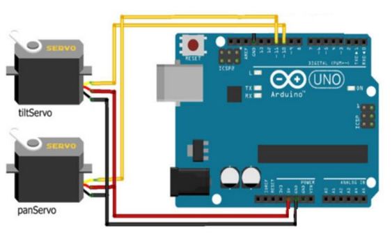
Electrical System:
For Sprint 1, we had a simple electrical system consisting of two servos and an arduino uno. The two servos for controlling the pan and tilt mechanism were connected with the signal wires to digital pins 11 and 10 respectively. The servo ground was connected to the arduino ground and power was connected to the 5V pin of the arduino.
Lesson Learned
Risk Identification for Sprint 2
- Integration needs to happen fast and continuously: We encountered technical difficulty in serial connection between the python code and arduino. The serial port of Arduino kept resetting and the Arduino did not always parse the information sent from the python correctly.
Risk Identification for Sprint 2
- Integrating raspberry pi, arduino and python together using a wifi/bluetooth connection
- Face detection algorithm cannot recognise face seen from too far below
- Using face detection algorithm to detect an individual's face specifically
- Processing speed of face matching algorithm might be slow for live face identification system