Final Sprint
Goals
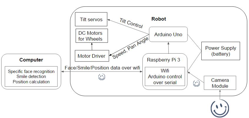
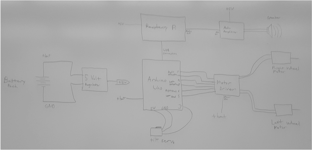
Integrated System Diagram
Goals
- Have a fully integrated, working system
- Include a sound system
- Complete documentation and website
Integrated System Diagram
Working System Demo
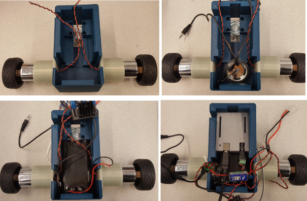
Photos of the Final Product
Development
Software:
In this sprint, we try to push the stretched goal of our product by adding the voice interaction to the user experience.
1. Weather Data Streaming
We use python API online to stream the most updated weather data information based on the current location (https://github.com/csparpa/pyowm ). By passing free registered API key and location data, we could retrieve weather data like wind, humidity, temperature and pressure. Below is the code we used to get weather data for our robot.
2. Text to speech
There are many text to speech libraries and packages for python and linux system. We use a very simple, standard package for linux system, GNUstep speech engine. (The download link and documenation can be found here: http://manpages.ubuntu.com/manpages/trusty/man1/say.1.html ) We've added this to allow our robot to read off the text that was generated above through the speaker.
3. Wheel Motor Control
As mentioned in the previous sprint, we had two major problems with using the servo we originally had. One was that it turned too fast one way, and the other was that since we could not do speed control, we had to use time.sleep() function to manually control the time that the servo will run for, and the time.sleep function messed up how the data was received over the wifi.
So for the final sprint, we replaced the servos with DC motors, which are connected to Arduino UNO through a motor driver. Controlling the motors was now even simpler than before. The motor driver accepts PWM signals, which can be generated by Arduino UNO's analogWrite function. We could control the speed of the motors too, but minimally, by controlling the PWM signal too.
In addition, the spinning direction of the motors can be controlled by inputting a digital signal high or low to the motor driver. Below is an example code that runs the motors.
Mechanical System:
Due to software constraints from wifi communication and pan control using time delay, we had to switch the rotation servos to the uxcell DC Motors which were very different in dimensions. Also, we included DC Motor Driver, Elegoo L298N Dual H Bridge Stepper DC Motor Driver Shield Expansion Development Board, and a sound speaker to be housed in the chassis.
We designed a very different 5 layered chassis which were 15cm by 15cm by 11cm in dimensions.
Pictures of 5 layered chassis Individual parts and Chassis Assembly
However, we did not go forward with this implementation because the base layer of the first and the last layer failed to print nicely and curved up at the edges partially due to the large size of the part and partly due to the constraints of the 3D printers we had access to.
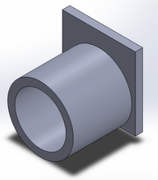
Instead, we modified our Sprint 3 design by attaching a motor holders to the sides, and fitting the speaker in the parts where servos were previously. The motor driver was placed in the cover with the Raspberry pi.
Instead, we modified our Sprint 3 design by attaching a motor holders to the sides, and fitting the speaker in the parts where servos were previously. The motor driver was placed in the cover with the Raspberry pi.
motor holder part
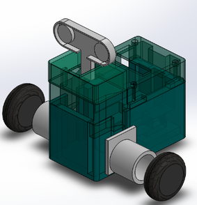
Final Mechanical Assembly
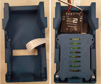
The chassis body houses the Motors, Speaker, Battery, Voltage Regulator and the UNO
The chassis cover houses Pi and the Motor Driver
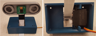
The head contains the tilt servo and the Pi camera module
Electrical System:
The final addition to our electrical system was the inclusion of a small audio amplifier and speaker to enable facelook to talk and play music. We determined that the most cost effective way to get a small audio amplifier (needed to boost the headphone level signal from the Pi to something with enough power to drive a speaker) was to get an inexpensive external computer speaker and disassemble it. We removed the audio amplifier from the Frisby FS-210NU USB powered speakers for this purpose. We soldered a small 50mm speaker to the output of the amplifier. The input to the amplifier was connected to a 3.5mm audio jack which was connected to the headphone output of the raspberry pi. Rather than use the USB jack to provide power to the amplifier, we decided to save USB ports on the Pi by powering the audio amplifier directly from the 5V regulator board. The other major change in the final electrical system was to change the continuous rotation servos for a DC motor with an integrated gearbox. The main idea behind this change was to allow us to use PWM to control the speed of the motors in both directions. The main design constraints for this motor was that it needed to operate at or close to our battery voltage, it needed to have sufficient torque to drive our vehicle, and the speed needed to be slow enough that small angle corrections would be possible. From these constraints we selected an uxcell 1:58 gear reduction, 87 RPM, 12V gear motor. In order to provide the higher current PWM drive signals required by the motor, we also included a motor driver board based on the L298N dual H bridge motor driver chip.
The final addition to our electrical system was the inclusion of a small audio amplifier and speaker to enable facelook to talk and play music. We determined that the most cost effective way to get a small audio amplifier (needed to boost the headphone level signal from the Pi to something with enough power to drive a speaker) was to get an inexpensive external computer speaker and disassemble it. We removed the audio amplifier from the Frisby FS-210NU USB powered speakers for this purpose. We soldered a small 50mm speaker to the output of the amplifier. The input to the amplifier was connected to a 3.5mm audio jack which was connected to the headphone output of the raspberry pi. Rather than use the USB jack to provide power to the amplifier, we decided to save USB ports on the Pi by powering the audio amplifier directly from the 5V regulator board. The other major change in the final electrical system was to change the continuous rotation servos for a DC motor with an integrated gearbox. The main idea behind this change was to allow us to use PWM to control the speed of the motors in both directions. The main design constraints for this motor was that it needed to operate at or close to our battery voltage, it needed to have sufficient torque to drive our vehicle, and the speed needed to be slow enough that small angle corrections would be possible. From these constraints we selected an uxcell 1:58 gear reduction, 87 RPM, 12V gear motor. In order to provide the higher current PWM drive signals required by the motor, we also included a motor driver board based on the L298N dual H bridge motor driver chip.

