Mechanical Design
Iteration One
|
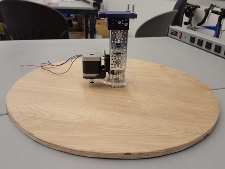
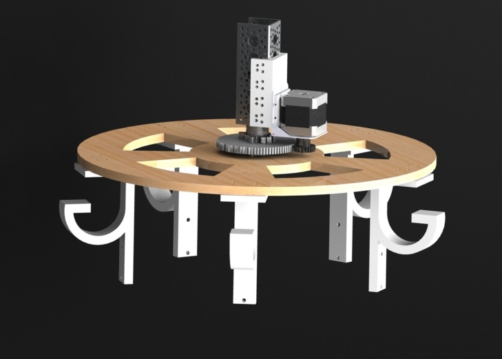
The most important factor of the mechanical part was getting the rotational motion. This was achieved using a NEMA 17 stepper motor. In order to get a large wooden disc to rotate, we designed our first iteration of our mechanical system as shown on the left.
|
|
1. Gears
In order to get gears of the appropriate size, with customized holes for integration, we laser cut our own gears out of acrylic. Two gears were made: (1) 3.58 in. outer diameter, 3.5 in. pitch diameter, 84 teeth (2) 1.58 in. outer diameter, 1.5 in. pitch diameter, 36 teeth. |
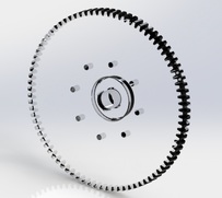
Large gear made of acrylic.
This one was attached to the shaft and the rotating disc.
|
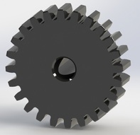
Small gear made of delrin. This one was attached to the stepper motor.
|
|
|
2. Connections
We have different ways of connecting different parts. There are largely four connections that we worked on for the first iteration. Attaching: (1) the disc to the large gear (2) the large gear to the shaft (3) the shaft to the channel (4) the the motor to the channel |
|
(1) Attaching the disc to the large gear The disc and the large gear were connected using an adapter-hub. Both the gear and the disc were screwed on the adapter-hub on each side. |
|
(2) Attaching the large gear to the shaft The large gear and the shaft were connected using a clamp hub. The gear was screwed onto the clamp hub and the hub was clamped on the shaft. |
|
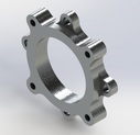
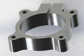
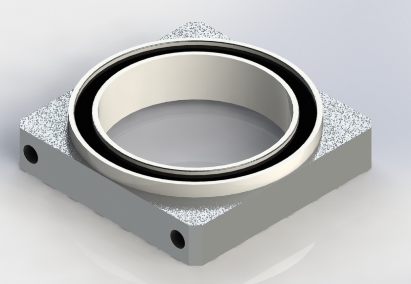
(3) Attaching the shaft to the channel The shaft was connected to the channel using a ball bearing. The shaft goes through the bearing and is fastened by a fastening ring. Bolts go through the holes on the sides of the channel and into the screw holes on the bearing. |
|
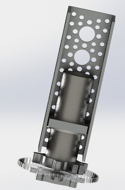
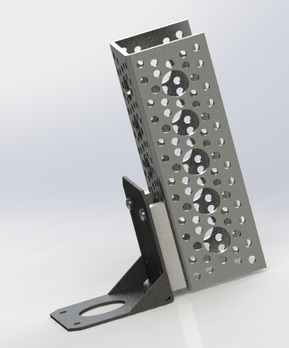
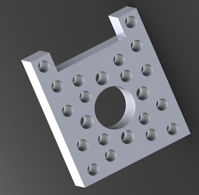
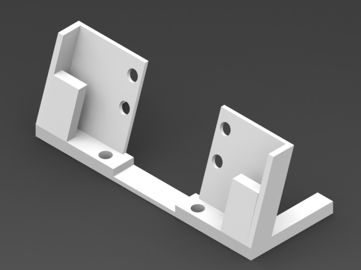
(4) Attaching the motor to the channel The motor was screwed onto a motor bracket. Then, this motor bracket was connected to the channel using a 3-D printed bracket as shown on the left. The holes match with the hole pattern on the channel. The top two ears are used to connect to the motor bracket using nuts and bolts. |
Iteration Two
|
From the first iteration, we noticed a couple problems. First, the disc was not centered. So, while it was rotating, it kept wobbling. Second, the bracket between the motor bracket and the channel was not accurate, causing the two gears not to line up perfectly.
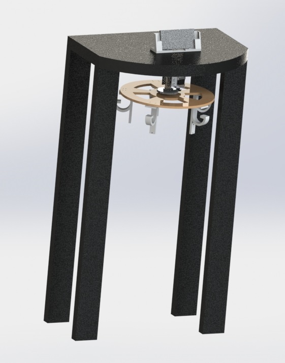
In our second iteration, we focused on fixing the two problems mentioned and adding hangers. We also created a standing desk that our rotating disk would get attached to in the end. |
|
|
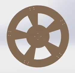
1. Iteration two of the wooden disc We re-designed the rotating disc. We laser cut the disc out of MDF wood. The disc was designed so that there were holes that were exact and centered to connect the disc to the adapter-hub. Also, we created holes on the five ends so that we would be able to connect our hangers to the disc. We made spacers in between to decrease some weight of the disc. |
|
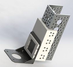
2. Iteration two of the bracket
We also re-designed the bracket connecting the motor bracket to the channel. We made it more sturdy by having the bracket wrap around the channel. Also, we have parts that slide through the slits in the motor bracket that is fixed with another rectangular bracket. All parts were screwed together using nuts and bolts. This bracket was also 3-D printed. |

|
3. Hangers Hangers were designed so that it would easily be screwed onto the disc. We made hooks shaped like a G so that things wouldn't fall off. There is an extended part below the G shape for IR sensors. The IR sensor will be screwed onto the hanger using the two holes on the extended part. The hangers were 3-D printed. |
|
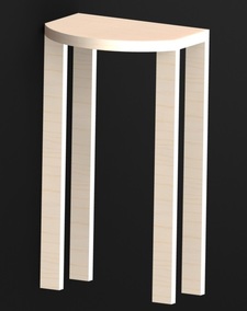
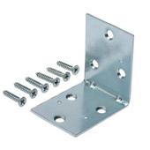
4. Standing desk We built a standing desk using wood and different types of brackets. Small L-brackets were used to initially fix the legs on place to the top of the desk. Then, we used larger triangular brackets to make the desk sturdier. The legs were cut at home-depot when we bought them, and the top of the desk was cut by us in the wood shop. |
Final Iteration
|
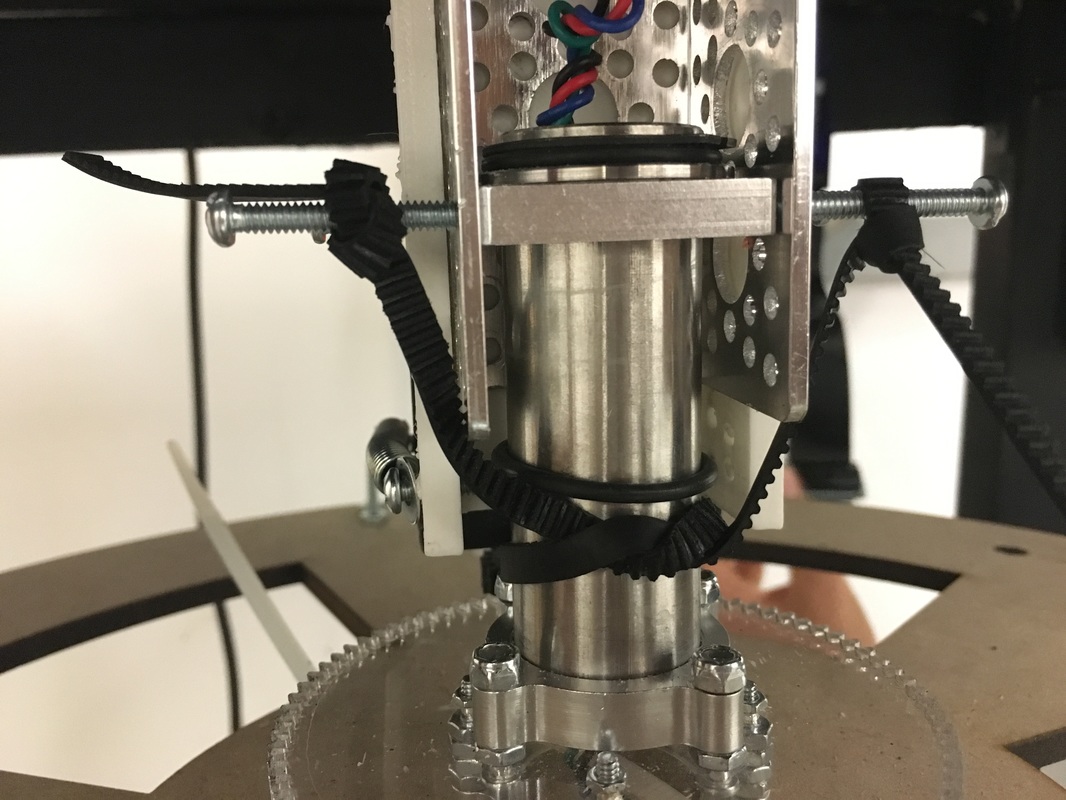
With most of our mechanical system functioning pretty well in the second iteration, we just needed a couple more touches to finalize our project. One huge problem we ran into moving on from the second iteration to our final one was weight distribution. The new wooden disc we made was too light that it was more shaky than we expected it to be. So, when we put items of different weight on the hangers, the disc started tilting, causing the gears to get out of place. At this point, we couldn't re-design our entire system. So, we found the next best solution - using a spring and a rubber band to keep the two gears in place. For our final iteration, we also attached the main system to the standing desk. We additionally created a display stand and attached it to the top of the desk. |
|
1. Getting the two gears fixed in place
To prevent the gears from getting out of place caused by the disc tilting, we wrapped springs around the motor and attached the ends of the springs two a bolt screwed in the channel. To get a more sturdier fixation, we wrapped a rubber band around the motor shaft and the shaft rotating the disk. This way, even if the disk tilts, the gears are still held in place. |
|
2. Attaching the main system to the desk To attach the main mechanical system to the standing desk, we used two L-brackets, one on each side part of our channel. One side of the L-bracket was screwed on the channel and the other side was attached to the desk. We drilled from the top of the desk and fixed the bolt using lock washers and bolts. |
|
3. Attaching the display to the desk
We designed and 3-D printed a bracket to hold the display in place. We made sure that there were holes available to screw the bracket onto the desk. We also have space on the back side of the bracket to have boards and wires connected to our display to go through. |
Learn more about the other systems!