Electrical Designs
Digitally Controlled OscillatorWe chose to use a digitally controlled square-wave oscillator in our final product. This uses the Arduino’s I/O pins to generate a square wave at a frequency determined by the key pressed. This never goes out of tune and is easy to tune initially by setting the period of the note. The code for this can be found in our github repository.
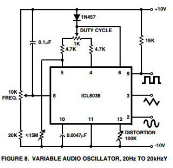
Initial Idea - Voltage Controlled OscillatorInitially, we wanted to generate these tones using only analog circuitry. The circuit that does this is called a voltage controlled oscillator (VCO). It takes in a control voltage and outputs a waveform with a frequency corresponding to the input voltage. There are many different ways to do this and our team chose to use an integrated circuit VCO - the ICL8030. This chip seemed ideal for us because it produced triangle square and sawtooth waves at frequencies all across the human hearing range. Like many VCOs this chip turned out to be temperature sensitive. It was so temperature sensitive that it would go in and out of tune within minutes and we decided not to use it.
The VCO was initially tuned by finding the relationship between control voltage and frequency for the particular arrangement we used. This was done visually using excel. This is a plot of the CV bits and the HZ output. The one we built was linear, but not ideal because note relations are exponential. Power SupplyWe currently are using a large power supply with variable voltage control. Our next step today is to change the power source over to two 9 volt batteries tied in series to create -9, 0, and 9 volt sources. Current analysis of the system determines that will be enough power unless shorts occur.
The voltage controlled amplifier is powered by -9 volts, 0 volts, and 9 volts. The Arduino, tuning fork evelope detector, and the ADSR envelope generator takes in 9 volts of power with the ground rail at 0 volts. The Digital to Analog Converter takes the output signal, 5 volts, and ground from the Arduino. |
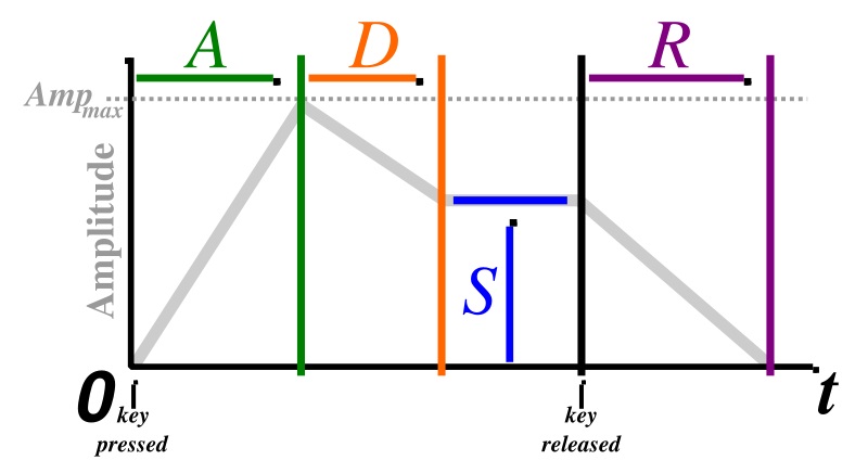
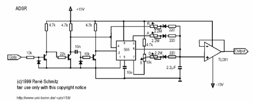
Attack-Delay-Sustain-Release Envelope GeneratorThe sound of a musical instrument is not only determined by the frequencies created, or the waveform, but also the way that the note begins and ends. This is called an envelope. Our synthesizer uses a 555 timer based circuit to create this envelope (see circuit diagram below). This envelope consists of four phases - Attack, Decay, Sustain and Release, giving it the name ADSR envelope generator. These are controlled by 4 potentiometers which determine the length of time for each phase. The output then is used to control the gain of the voltage controlled amplifier.
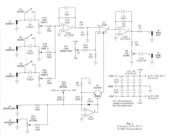
Voltage Controlled Amplifier,The final stage of our synthesizer is the voltage controlled amplifier. This part of the system essentially puts everything together. It consists of two major pieces - a summing amplifier, and an amplifier with a variable gain. The summing amplifier combines the signals from the different VCOs and if necessary corrects and DC offsets that may have been present in the signal. The summing of multiple VCOs with different frequencies and waveforms is what creates some of the rich and unique sounds that many synths are known for.
This part of the circuit uses the voltage generated by the envelope generator and from the tuning fork amplitude output to modify the gain of the amplifier. This integrates all of the signals and outputs the final sound from our synth. |
Circuit Pictures and Video
|
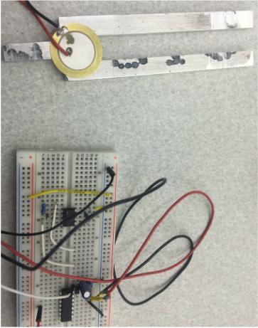
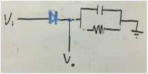
Tuning Fork Control: The scope is showing the output to the tuning fork circuit. As you can see, there is a sharp peak whenever the tuning fork is hit and after that, it quickly decays.
|
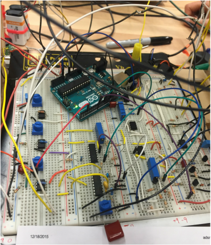
Attack-Delay-Sustain-Release Control: The scope is showing the output of the voltage controlled amplifier. As you can see, when any of the ADSR sliders move, the shape of the wave changes.
|
Circuit Diagrams
|
Cost of components and
where to find them is in our |
