Documentation and Blogs
Documentation and Blogs
Throughout the course of the project, we documented significant steps in our progress with blogs.
Dynamics
We could abstract our self-balancing unicycle to an inverted pendulum moving on a cart. There are two second order differential equations that describe the motion of this system. First let's look at the diagram of the inverted pendulum:

This following derivation relies on the assumption that the beam is massless and there is no friction within the system. After doing research online, we found that there were two main ways to derive the equations of motion for this system. One approach is use Lagrange equations, which considers energy. The other approach is to use Newton's Laws. Either way, we end up with the same two equations:

This could be rewritten and solved for linear acceleration of the pivot point as well as angular acceleration of the pendulum. With that information, a MATLAB model was created with the state space as position, velocity, angle, and angular acceleration. This model took in a set of initial conditions and visualized the behavior of the cart and pendulum. While this was not particularly useful for our execution of controls, this helped us understand the mathematics behind the system. This math was further investigated as explained in the Controls blog post.
Controls
While considering the self-balancing unicycle project, we started looking into how other people approached the problem. We quickly came across terms such as the inverted pendulum and controls. With more research we converged to the idea that the problem that we were trying to solve was ultimately an inverted pendulum problem.
The inverted pendulum problem is a classic introductory control theory and dynamics problem. The dynamics of the problem will be covered in a separate post. The problem involves a pendulum with its mass above its pivot point. With just the pendulum and mass, the system is unstable. However, with the addition of a control system, it becomes possible to maintain the mass in the completely upright position. The simple explanation of the controls at hand can be well modeled with the cart and pole model. This involves sensing changes in the angle and having the cart move to balance the disturbance.
In our research we came across two methods for balancing an inverted pendulum. The first is by moving the pivot point horizontally when the pendulum falls. The second method stabilizes the pendulum without any feedback. This method, called Kapitza’s pendulum involves oscillating the pivot point rapidly in the vertical direction. At this point, we acknowledged that we were a deep grave team, however, we weren’t in pursuit of the center of the earth. As such we chose the first method.
In our case, we decided to pursue a PID control loop. PID stands for proportional-integral-derivative. The basics of this involves calculating the error between the current position of the system and a desired set point and then applies a correction based on proportional, integral and derivative terms.
In sprint 1, we developed a simple cart and pole model by iterating on our POE Lab 3 deliverable. This code can be found here (https://github.com/mpatil99/UNO). All the controls iterate on this basic model. This model relies purely on the angle on the pendulum in order balance. We talk more about the other sensors in another post.
Power Requirements
In order to determine specs for our motor, we needed to calculate how much torque was required to accelerate the inverted pendulum in the opposite direction from which it was falling. By solving for the equations of motion using Newton's Law, we were able to find a relationship that we could use to estimate this torque. Below is a picture of the inverted pendulum problem we did for homework in QEA this semester. The left boxed equation shows one equation relating acceleration of the pivot point to the angle of the pendulum falling. By making the assumption that angular acceleration is 0 and that the pendulum starts at an initial angle of 5 degrees off center, we could develop a rough idea for how much the pivot point would acceleration and consequently how much torque we need our motor to output to balance that acceleration. Simplified down, that equation then becomes:
- gtan(5 degrees) = a
- F = T/radius of wheel
- a = F/mass of system
Motor Torque Testing
One of our first concerns for the components of the full-scale unicycle was the motor. In the first few days of the project we realized that a scooter motor was most likely to be appropriately sized while still in our price range. A NINJA was happy to bring us two large scooter motors left from previous POE classes, along with a massive 12 volt battery weighing 12 pounds.
The quick discovery of free motors, that seemed ideal at the time, put motor selection out of our immediate focus while we put together our first iteration, an inverted pendulum on a four-wheeled cart. However the motors' poor performance brought motor selection back into focus. While we were designing the frame, we started to converge on a selection of materials, and therefore mass. With this, and some nifty knowledge of dynamics, we were able to calculate a torque requirement for our unicycle with and without a rider. This gave us the goal of achieving around 4 newton-meters for an unmanned unicycle. So we wheeled three hefty power supplies into the MatSci lab and hooked up our motor with a six inch aluminum lever in the Instron. The results showed that the motor had a stall torque of around 1.4 Nm and if we were to make a conservative bet with motor torque outputting a max of .7 Nm, we would need a gear ratio of roughly 6:1 to achieve the 4 Nm we needed.
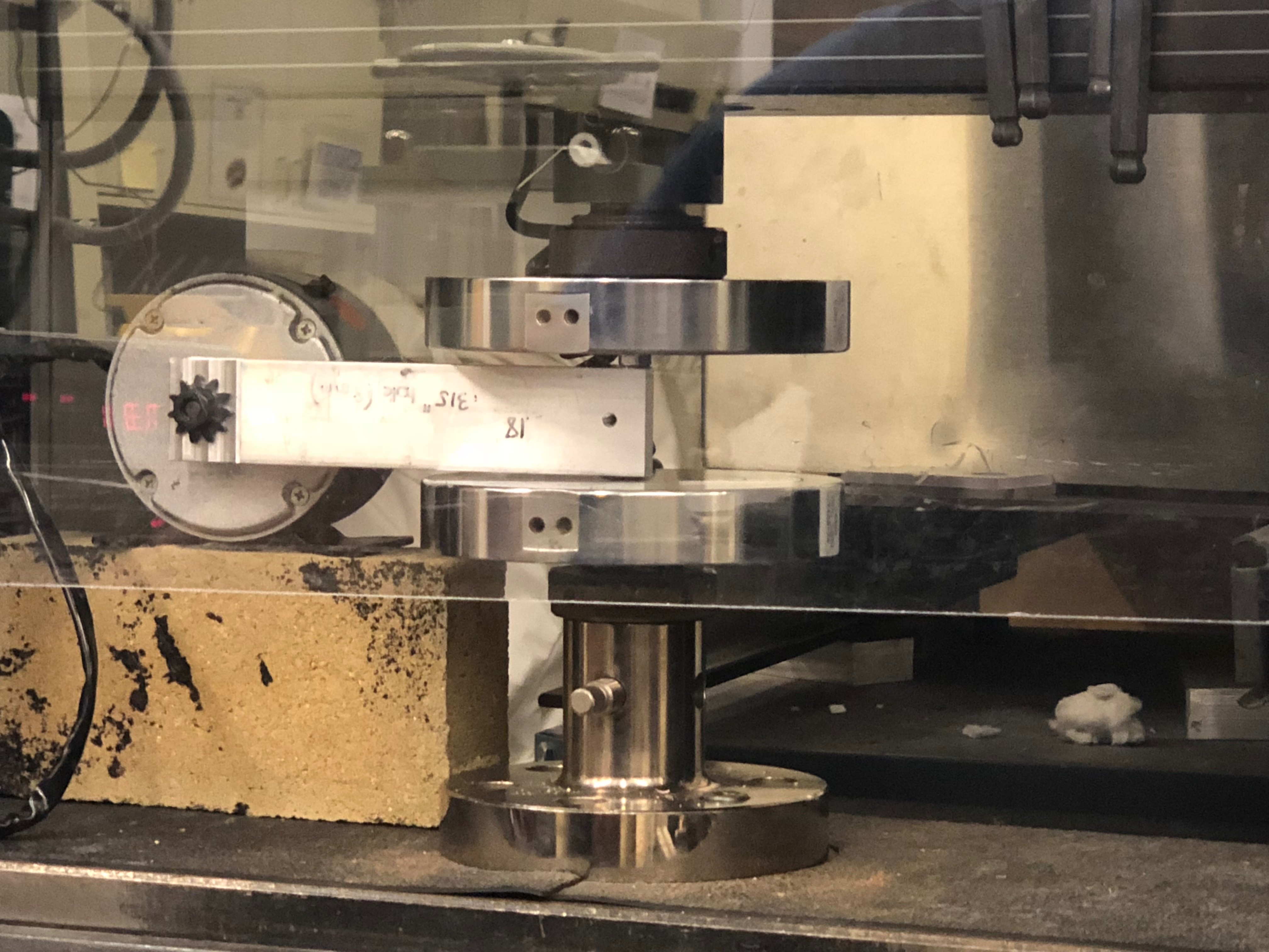
The motor testing firmed up our selection and gave us an important step forward for the design of the frame. We also were able to order our entire drive train with the motor specified making us much more confident about the project in general. -George
Gear Ratio and Belt vs. Chain
On Selecting Gear Ratio Earlier on, as described in the power requirements section, we had figured out that we wanted the wheel to output roughly 7 Nm of torque. After conducting testing on the scooter motor we had available in class, we calculated that we needed a gear ratio of approximately 6 to reach that value. The stall torque of the motor, through testing, was found to be 1.4 Nm. Since the torque-rpm curve is a linear relationship for a DC motor, we made the conservative bet that the motor could reliably output an average torque of roughly .7 Nm. That being said, a gear ratio of 6 would bring the torque on the driveshaft to be 4.2 Nm. This allowed us to achieve our goal of 4 Nm when the motor is actually running (the motor does not move at stall torque).
Since the motor came with a driving sprocket, we just needed to spec an accompanying driven sprocket. The driving sprocket is an 11 tooth, ANSI 25 chain sprocket. This means that a 66 tooth, ANSI 25 chain sprocket would give us the gear ratio of 6 we need. The cheapest supplier we could find for 25 series sprockets was Andy Mark, and coincidentally, the largest tooth sprocket they sold was a 66 tooth sprocket.
-Update on Driven Sprocket- It turns out that the 66 tooth sprocket purchased from Andy Mark is out of stock for at least 6 weeks. They had advertised that it was still in stock, but did not notify us of the real status until I called them a week and a half later. Fortunately, the wheel assembly we ended up purchasing did come with a sprocket, and it happened to come with a 80 tooth sprocket. That was fantastic considering we now had a gear ratio of roughly 7.2:1 which would supply us with more than enough torque.
On Selecting Belt vs. Chain
This was another design decision that had to be made alongside the setting the gear ratio for the drivetrain. Belts would provide us near-instantaneous transfer of torque from the motor to the driveshaft. This is desirable because of our lack of experience testing inverted pendulums. We did not want significant lag between sensor input and motor/wheel response as it could undermine the sensitivity of our control efforts. However, in order to implement a belt drive, we would need to make custom pulleys for both the motor and driveshaft. Purchasing the right sized ones were too expensive of an option and fabricating them would take more time than we liked. Furthermore, the team did not have significant experience working with belt drives.
The main benefits of using a chain drive were mainly that both the motor and the wheel assembly we were looking at, came with sprockets designed to be equipped with chain. Using these sprockets as opposed to making custom pulleys would save the team a lot of time. Furthermore, members of the team had prior experience working with chains through experience on other project teams. The question was then did we value near-instantaneous torque transfer or a quicker fabrication schedule? After talking to members of the POE teaching staff, we decided that the increased fabrication schedule was too great of a risk and that the delay within the chain drive should be small enough that it shouldn't be a large failure mode in our controls.
Battery Troubles
After testing our motor with the power supply setup we quickly realized that we were not supplying anywhere close to how much current was necessary for the final product. In order to figure out a battery that would supply enough current we looked into the max possible current draw of the motor. We found that the motor could draw up to 16 A.
While considering battery options, we already had one 12V 15Ah sealed lead-acid motorcycle battery. We thought about Lithium Ion batteries, however, we really didn’t care about energy density so we decided to stick with sealed lead acid batteries.
We had some trouble sourcing the appropriate batteries and had to go to a couple of different shops around to see what was available. All options we found were either too expensive, too heavy, or too large for our application. After reducing the requirements for our system, we settled for online purchased batteries. Each of the batteries are 12 V 10Ah sealed lead-acid batteries, weigh roughly 13 lbs, and are 6"L, 2.5"W, 4"H.
Selecting a Motor Controller
The Motor Controller selection followed from a few key variables. The variables are the current on the High Voltage path, the voltage required by the motor and supplied by the batteries, and cost.
We determined that we wanted support for at least 30 Amps. The batteries supplied 24 Volts and we wanted to keep the cost under $30. The Cytron MD30C met our requirements pretty well. https://www.amazon.com/gp/product/B07L6HGFWY/ref=ox_sc_act_title_1?smid=A2YOQJANPWZAKX&psc=1
Sensors
In terms of sensors, we determined that we would need two different types of sensors: a gyroscope and a motor encoder.
The gyroscope would be used for monitoring the error in the angle. We were pretty lucky here as we received a pretty robust sensor in our first sprint. We learned how to communicate over I2C and were able to get absolute angle measurements with relative ease. One of the harder challenges was the mechanical mounting of the sensor. For the preliminary testing round we taped a mini breadboard to the top of the pendulum. This sensor was used for the inner PID loop which outputted a certain motor PWM for a displaced angle.
The second sensor necessary for the system to operate was a motor encoder. This would give us the speed of the motor. This interaction would be part of a second PID control loop which would greatly improve the precision of the balancing of our system. Furthermore, this would help us actively adjust for discrepancies in motor operation. When it became evident that we would not be able to have an adequate solution to this system, it became clear that we would no longer be able to balance our system. It was here that we decided to pivot.
Structural Frame
The frame for the unicycle was modelled to prioritize ease of manufacture, rigidness for maintaining accurate angle measurements across the system and to have an overall weight that works for the calculated dynamics. We choose to use .065” thickness 2” square steel tube because it was easiest to weld and notch in our shop. We also choose to use welded connections as we were worried about the bolt preload applied by the tensioning of our axle. Steel was chosen over aluminum due to overall cost of aluminum extrusion and the difficulty to weld aluminum tubes due to our novice experience in TIG welding. We prioritized simplifying the system’s overall number of components to minimize our mechanical fabrication time. This resulted in the need to only make four cut tubes for the frame and no parts to be made on the mill or lathe. All sensors are integrated into the frame utilizing 3D printed mounts. The frame enabled easy modification without the need to worry about it breaking.
Unicycle Training
As one of the original proponents of building some sort of automated unicycle, the unicycle has always been the real motivator for me. Imagine walking though the O when you leave the PoE lab at 2:00 AM and seeing a lone unicycle, no rider, doing laps around the oval. This fever dream of a project is what motivated me to dig a deep grave.
I believe that if one is to build a unicycle, they must first gain an appreciation of the unicycle. To this end, I've pushed since the beginning for the team to learn to ride unicycles. I managed to procure a decades-old unicycle from a friend and steal a pedal to complete it. None of us had ridden a unicycle before so we were looking forward to mastering it. In every sprint review, I mentioned our plans to ride unicycles as team bonding.
The night before our third sprint review, we finally took the time to do the real work and get on the unicycle. Frankly I think the entire first sprint should have been learning to ride unicycles, with our sprint deliverable being a cadre of expert cyclists. I was overconfident, believing my experience on two wheels would translate to a single wheel. I realized my mistake when I fell face first on the ground. Nonetheless we each took our turn flailing around painfully on the unicycle until we decided our optimism was sufficiently crushed.
Although I was fully expecting to serve as our team's crash test dummy (unicycle riding was one of my goals for the semester), we ended up with a scooter. As I already knew how to ride a scooter, I felt I should at least learn some scooter tricks. Unfortunately, due to time constraints, this will have to be left for SCOPE.
The Pivot
Our intentions and goal was always to fabricate and control a self-balancing unicycle. Unfortunately, during our last sprint we ran into multiple issues with the implementation of rotary encoder. Our team had reached out to multiple project teams on campus and found ourselves at a crossroads two days before the final presentation. We had concluded that despite any efforts we may put in, it was certainly impossible to have self-balancing implemented without the proper sensing suite. Thus, we decided to make the bold decision to pivot our design to an electric scooter. This was done due to the fact that we found it more appealing to present something functional to the teaching team and our peers rather than speaking about our failed self-balancing unicycle. In order to make this vision a reality we had to make several modifications to the existing structure.
Our scooter required a front wheel assembly, handlebars, power controls, battery integration, and general organization of electrical systems. We chose to use our existing unicycle as a rear wheel assembly to drive the scooter and then chose to use the front portion of a Razor scooter as it already contained a front wheel assembly and steering column. We modified the steer column to be longer by cutting on the top handlebars and welding it to a longer piece of aluminum. We used wood scrap to create the deck of the scooter to create a more comfortable ride experience. For controls, we 3D printed mounts for a dead switch, accelerator, and decelerator to be attached to the tube of the handles. These controls were then wired through the steering column to the electrical system mounted on the battery enclosure. In the end, we were able to completely convert the unicycle to an electric scooter in 36 hours. This final product is much more reliable and easy to use than our previous expectations. We are proud of the result as we worked hard to have something worthwhile and presentable during final presentations. We hope to keep working on the scooter to improve safety and speed. We also plan on replacing many components like the motor control and the front wheel to improve overall performance.