MECHANICAL DESIGN
The mechanical designing passed through many iterations until it reached its final state.
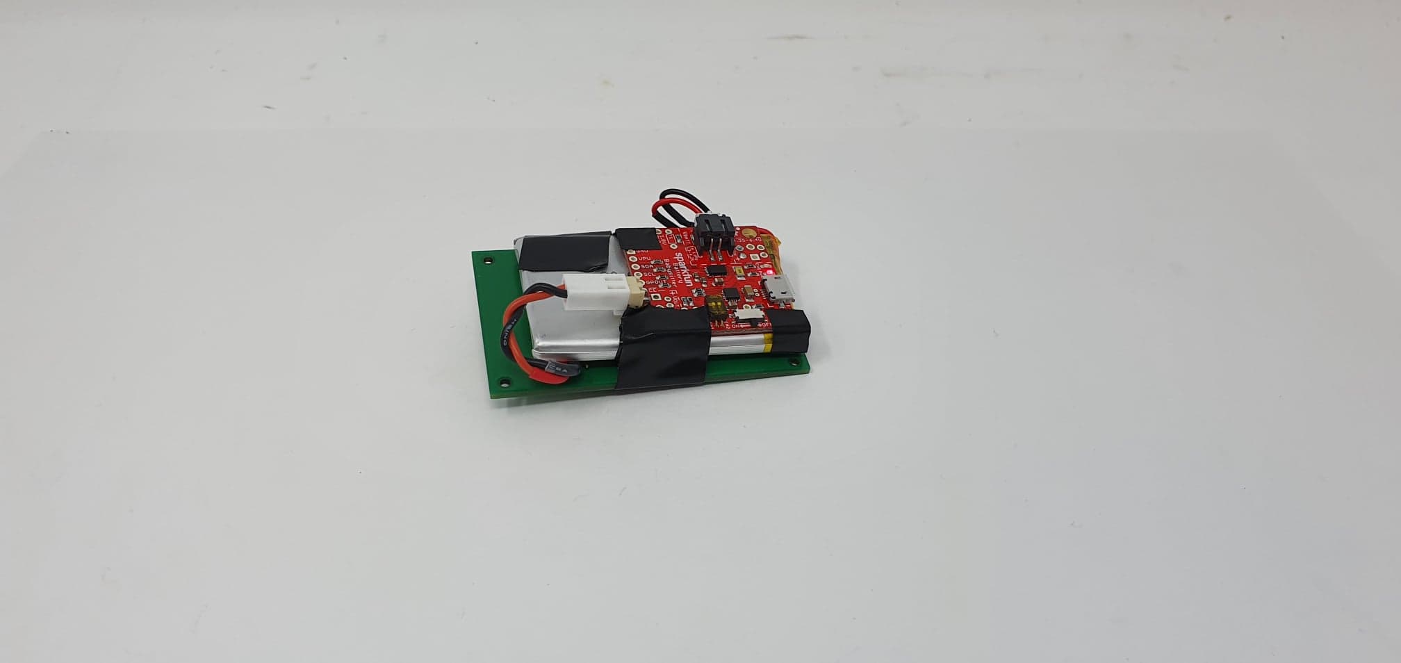
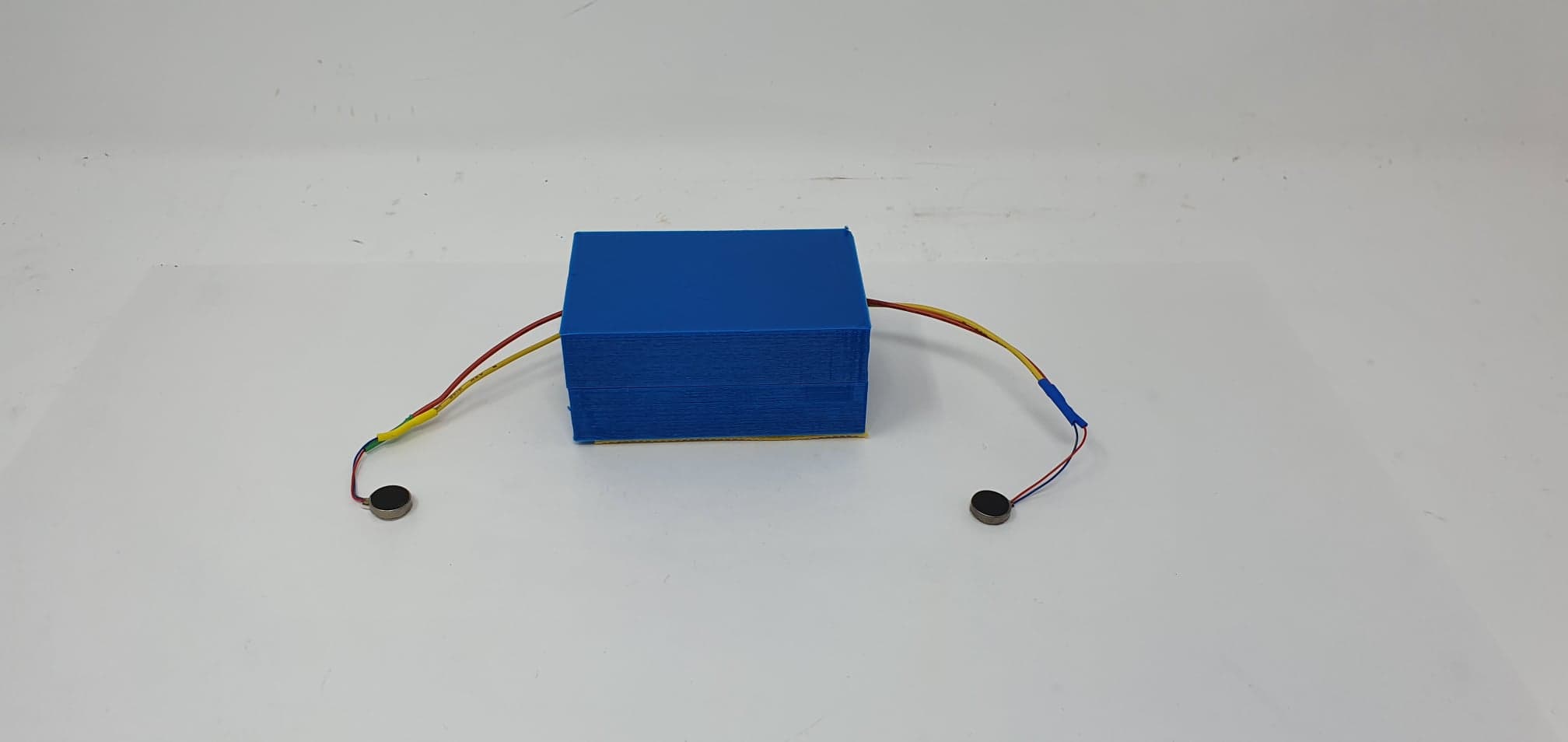
All the electronics are stacked together in order to minimize the volume they occupy. To stack the electronics we used double-sided tape between the PCB and the battery. Electrical tape was used to attach the battery-babysitter to the battery.
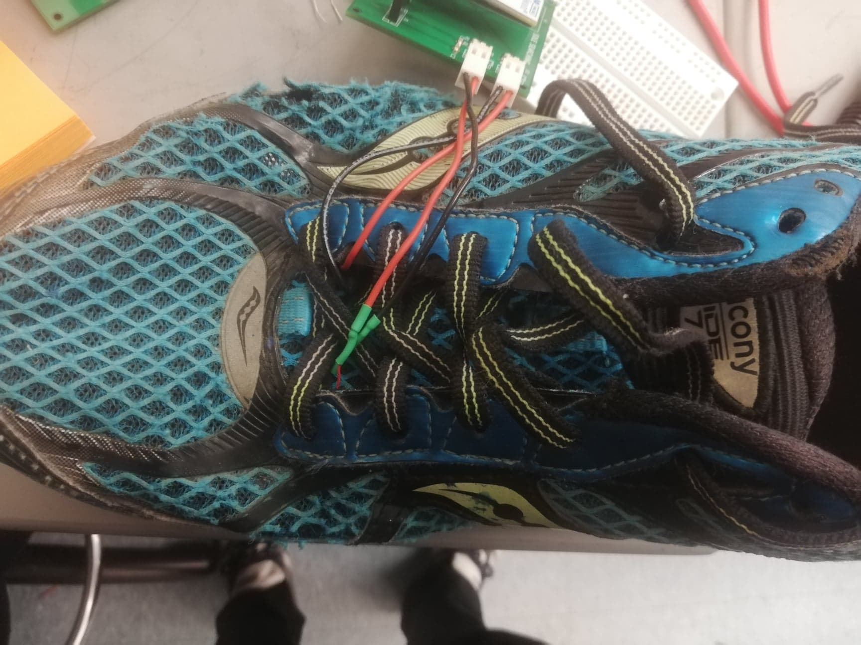
The vibration motors of the system were glued inside the shoe to the top left and right corners of the front part. (see photo below). The cables from the motors are attached directly to the PCS and their connectors allow the user to very easily detach them.
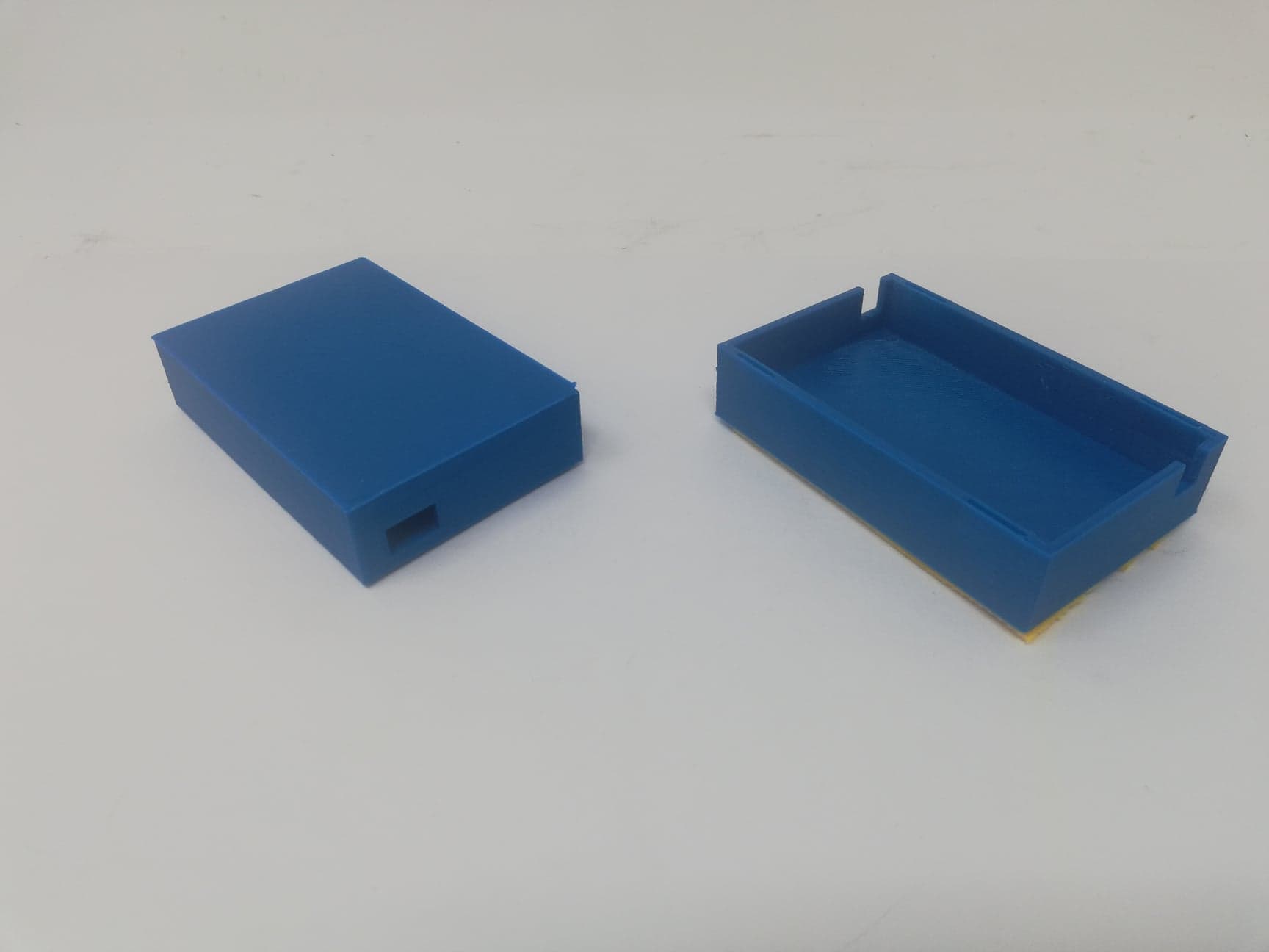
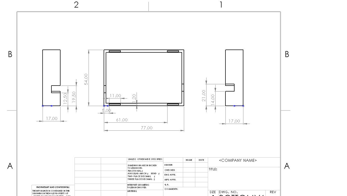
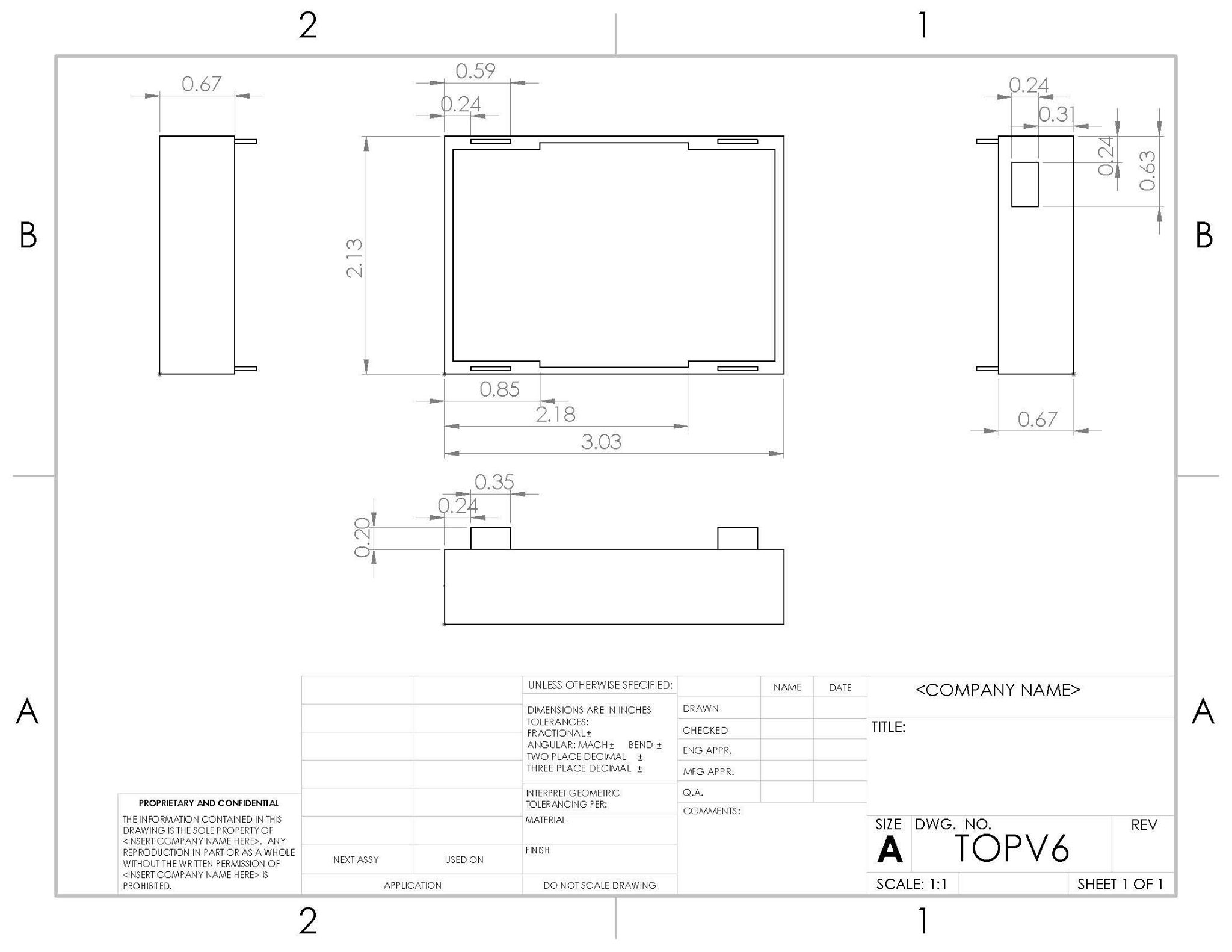
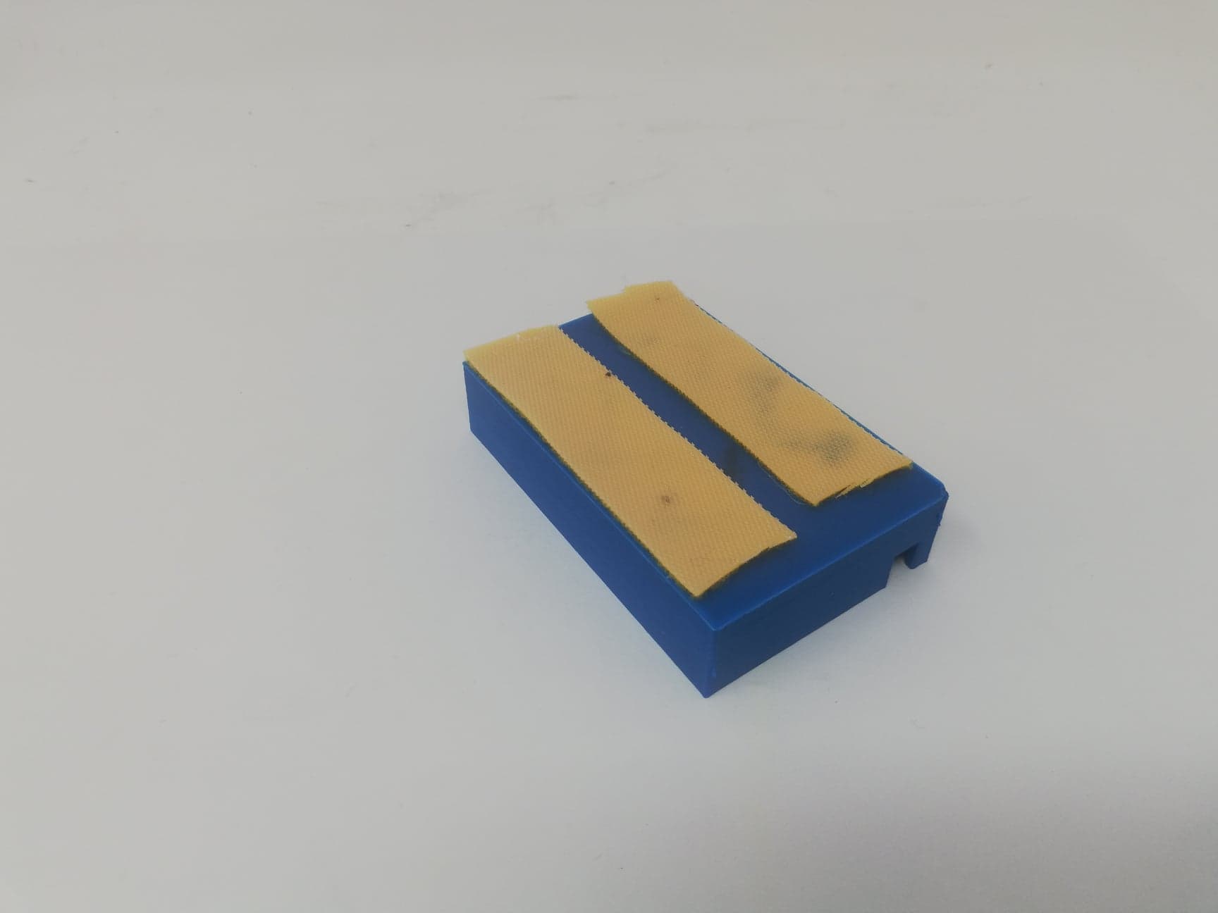
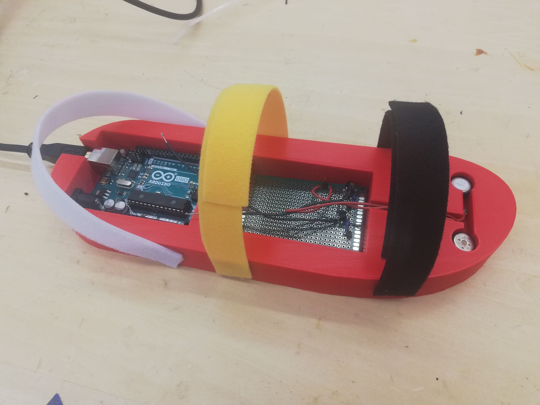
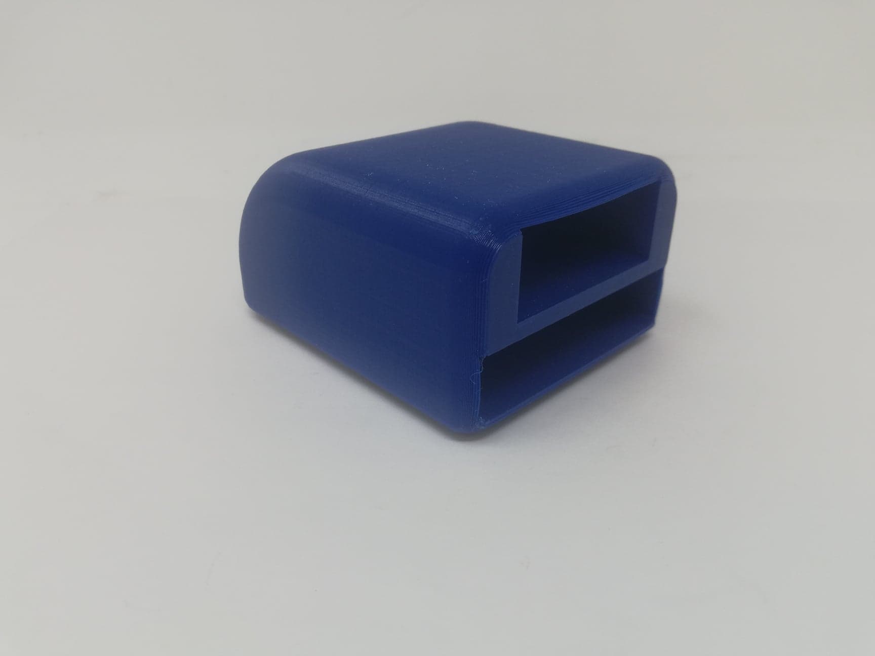
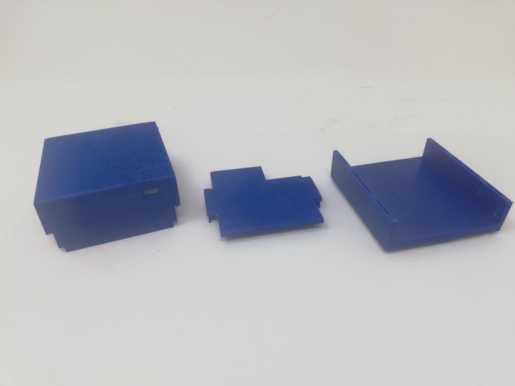
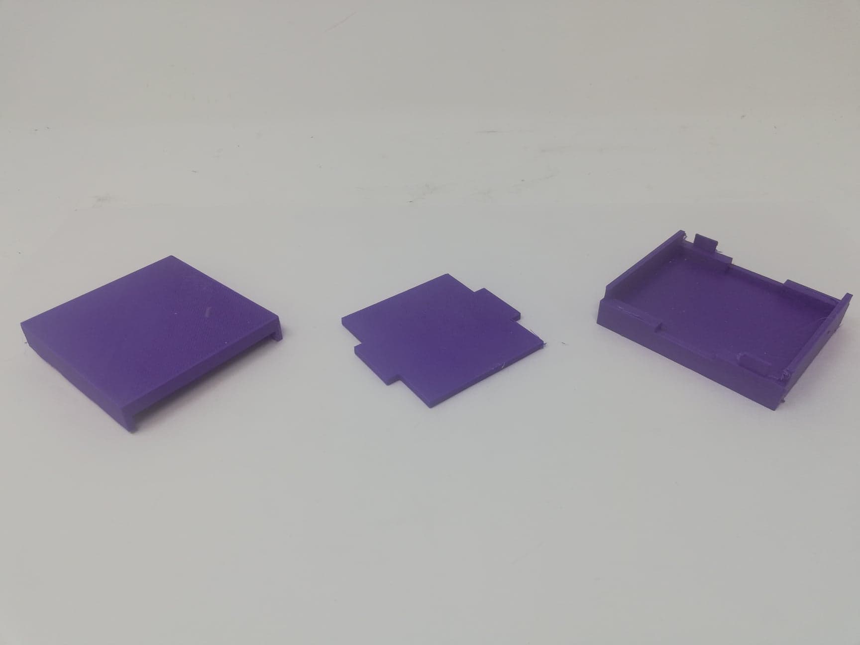
A case for the electronics was designed, 3D printed and tested. Until we reached the final design that you can see below we experimented with different sizes and shapes. The final casing is 77mmx54mm and weights just 42g without the electronics. After printing the case, we tested its strength by applying loads on it in order to understand it limits. We wanted to make sure that the electrons would be protected is someone stepped on the case. The final design did not break when one of the team members applied their full weight on it. One of the designs of the preview had failed this test. The electronics case also has holes on the side to allow for the battery to be charged with a micro USB cable as well as for the tables of the motors to be able to reach the PCB. Below you can find a photo of the case as well as the drawings and its dimensions. (The dimensions are in mm)
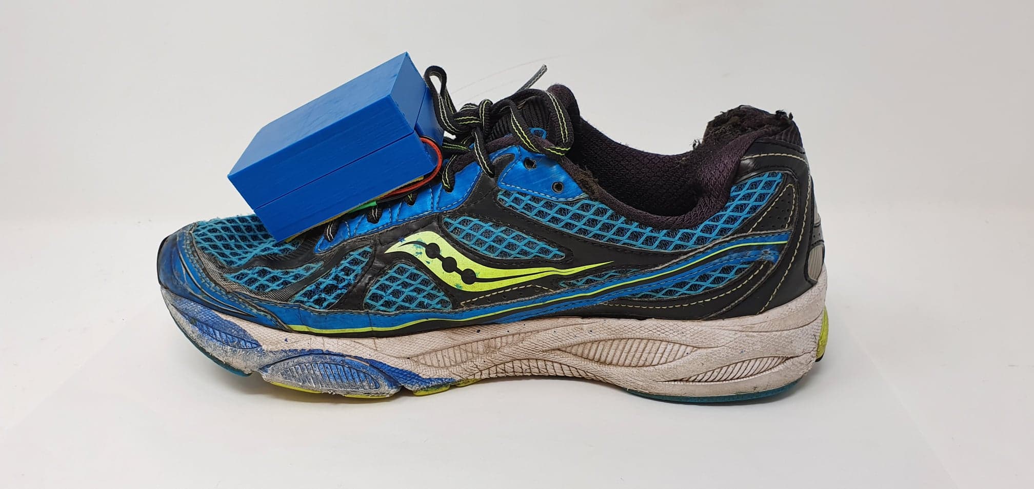
The stacked electronics and battery are installed inside the electronics holder with the two motors coming out from the side.
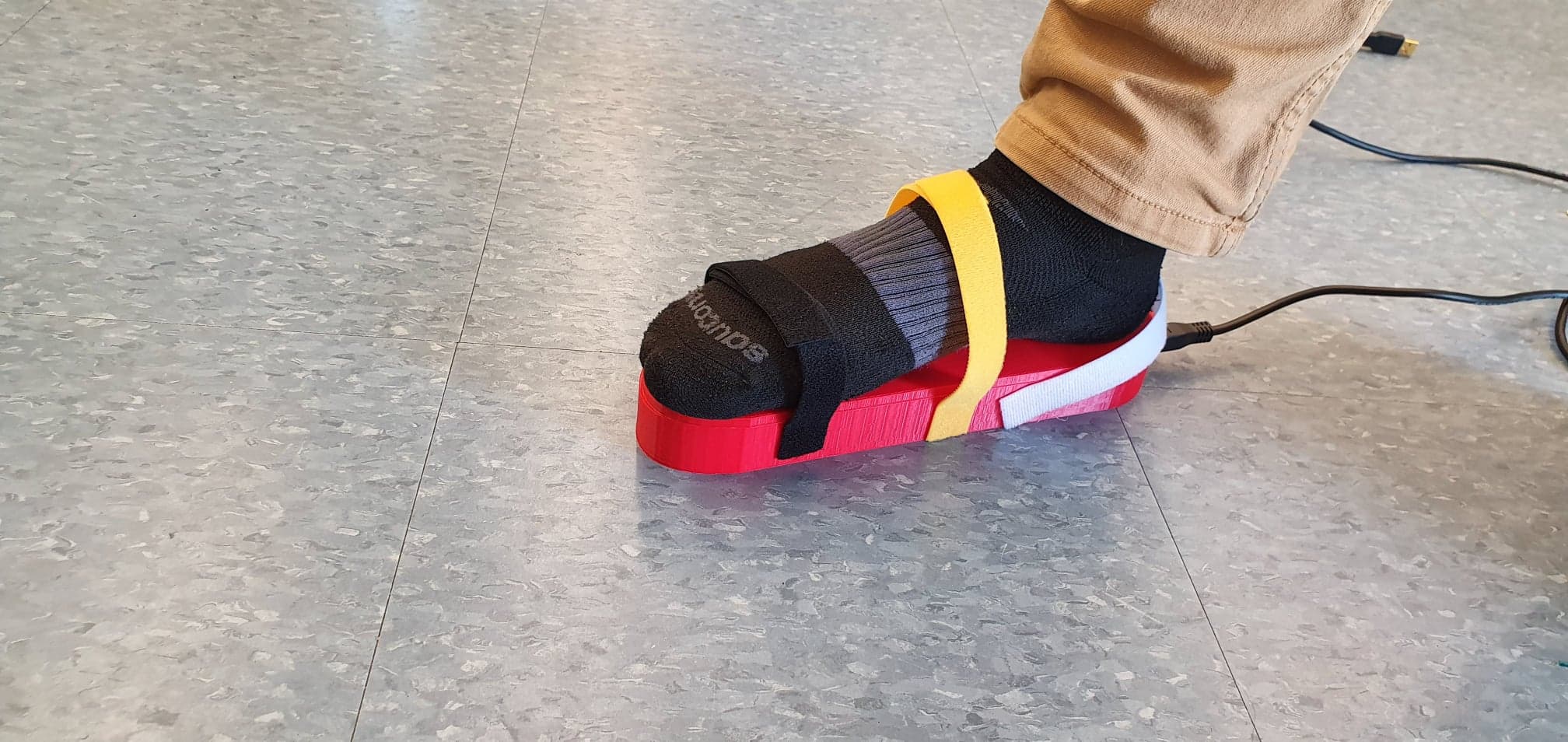
The case of the electronics attaches to the shoe lashes using velcro, this way it is easy to detach the electronics when the smart shoe features are not used.
ITERATIONS
Iteration 1
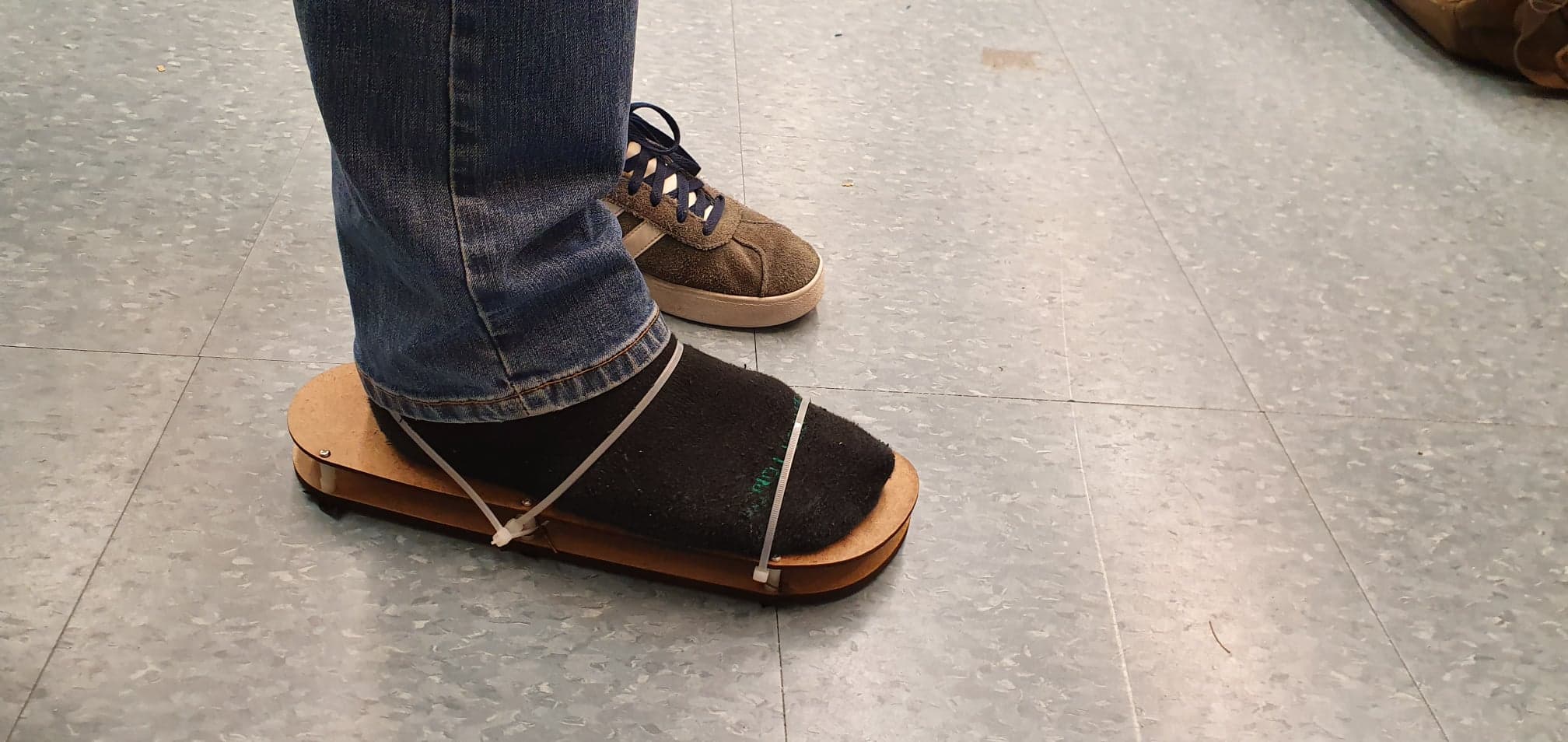
The first iteration of the shoe design was made out of two laser cut pieces of hardboard held together by screws and nuts. The pace between the two plates would be used for the electronics bay. This way of connecting the plates was not very successful as it could not handle the weight of a single person.
Iteration 2
In the second iteration, the shoe was 3D printed using PLA and had space to place the protoboard, the Arduino as well as the motors. The prototype was successful as the weight of the person wearing the shoe was distributed in more are. However, velcro straps were used to wear the shoe at that point so we had to improve the design of the shoe.
Iteration 3
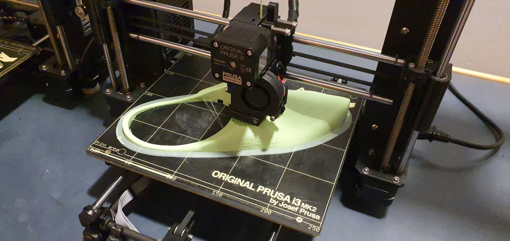
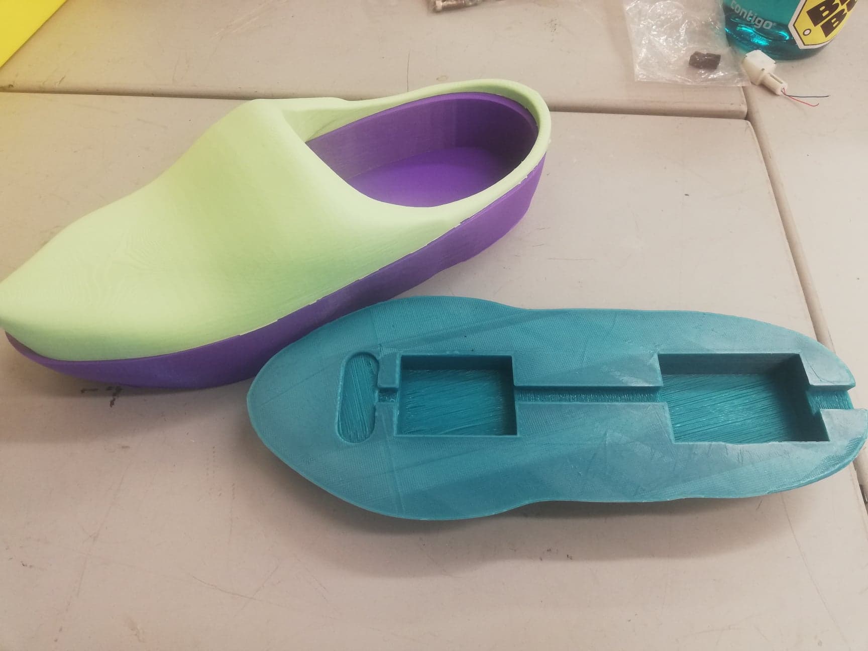
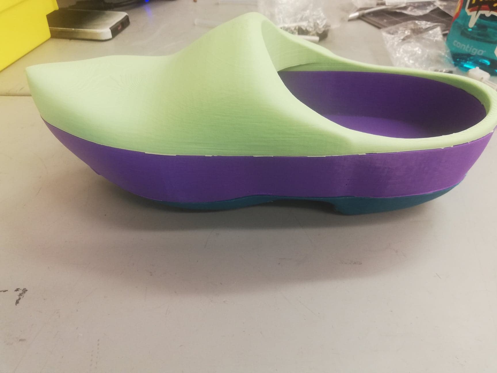
For the third iteration, we 3D printed a whole shoe in three layers were the first layer (Dark Green) had to space for the electronics and the other two were used so the shoe can actually we worn. For this design, we were limited by the size of the printers so we could not make a shoe big enough for an adult.
At that point, we realized that making an actual shoe would be a very hard task to undertake and we had a very limited amount of time left in the project. So we decided to pivot from designing shoes into modifying existing shoes and making an electronics holder.
Iteration 4-7
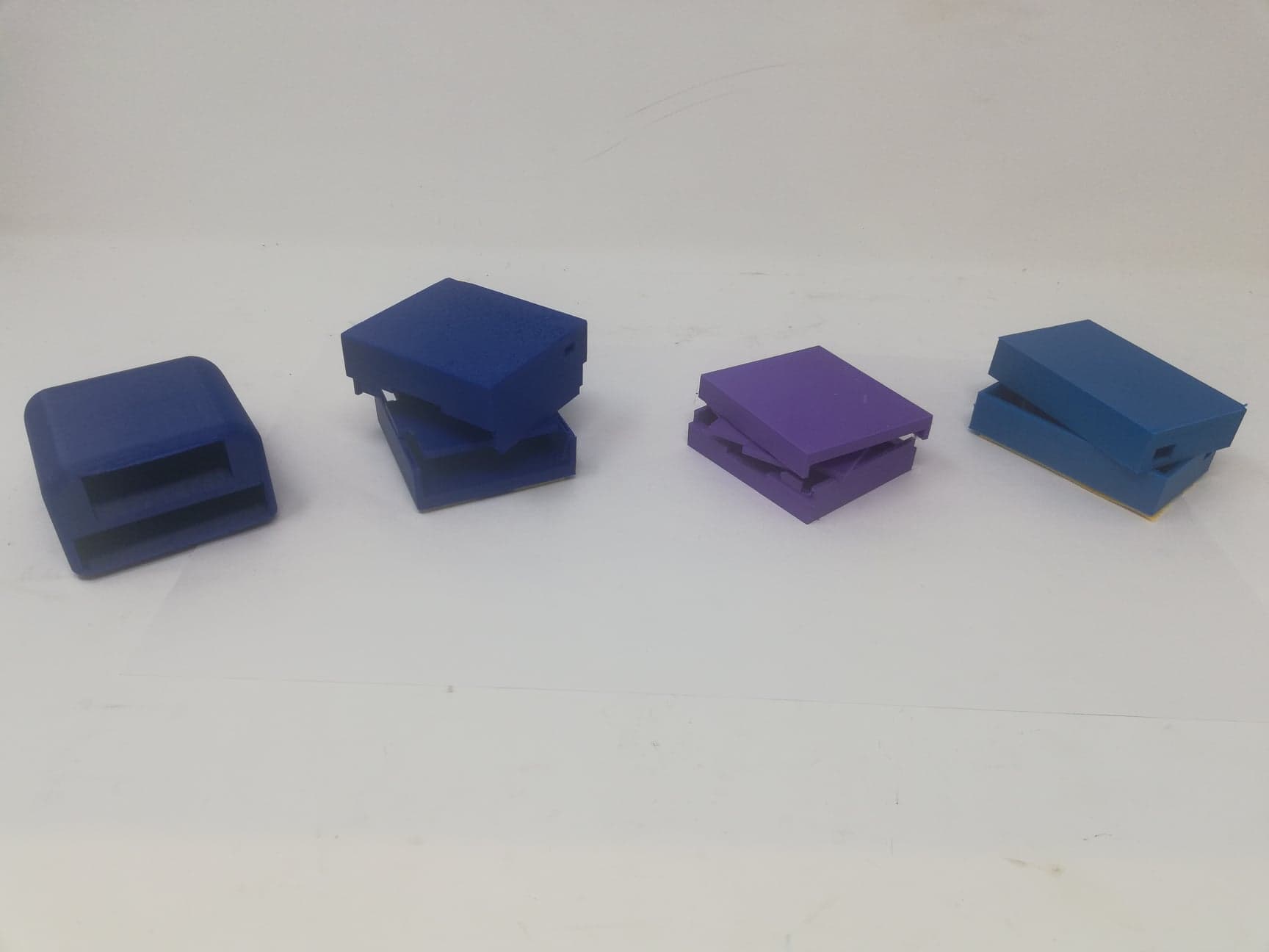
Below you can see the four different designs we made, each a bit different, but most importantly small and lighter. All of the four iterations used velcro to be attached to the shoe and had holes for the cables to be able to pass through.
Iteration 4
The first electronics holder was big and bulky, it weighed 96g. It had slots on the side to slide in the electronics and battery separately. However, there was a lot of wasted space and extra weight.
Iteration 5
This iteration had a much smaller and lighter design but it was still bigger in size than our final product. The battery and PCB were still separated, but with a smaller and thinner plate.
Iteration 6
In this iteration, we used the same dimensions, but we minimize the thickness from all of the walls.
Iteration 7

For the last iteration, we decreased the total dimensions of the holder and made the decision to stack all the electronics together in order to minimize the inner volume of the holder.