
ELECTRICAL DESIGN
A summary of the electrical system in Sole Searching - the important ingredients that can be used to prototype a similar system.
We developed and prototyped a system which is capable of taking map instruction via bluetooth, and producing the necessary output for indicating direction using vibrating motors. We started with prototyping the bluetooth module circuit on a breadboard and simulating the idea of directional aids using Arduino IDE. We worked towards a functional PCB with an ATMEGA 328P-AU microprocessor which does all the computations and controls the I/O devices and can be safely mounted in a shoe - a product that can be integrated with mechanical system as well as the software system in an easy and intuitive manner.
DESIGN PROCESS
A step-by-step walk-through into our design phases and a technical overview.
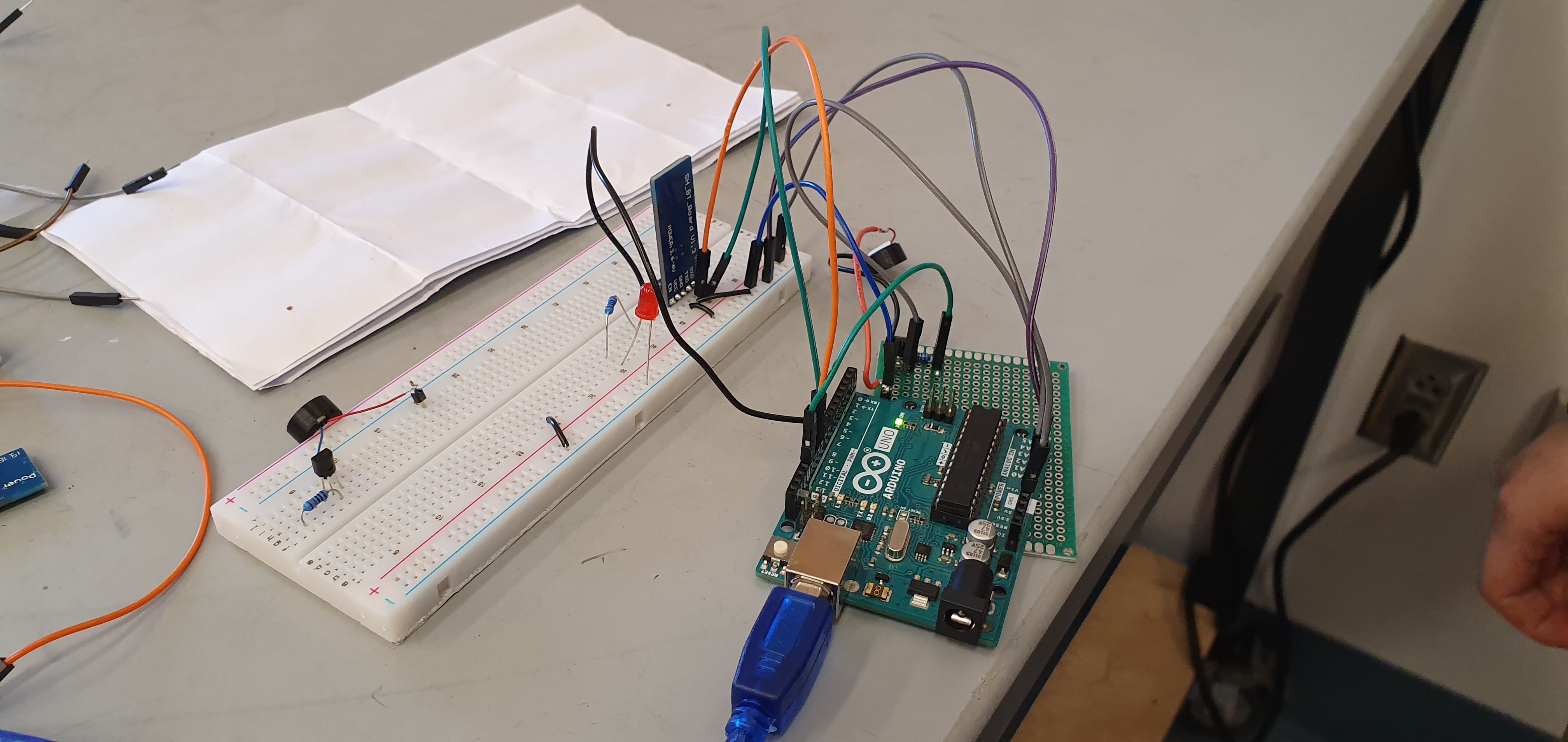
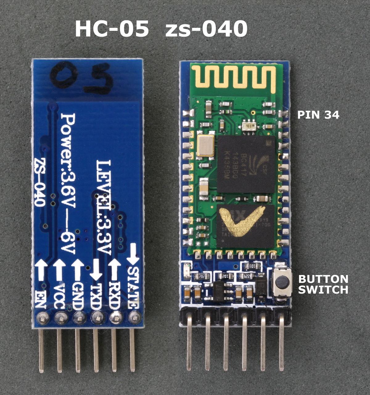
- Exploring various parts and possibilities - We tested the Bluetooth Module (HC-05) and made a simple mobile app using the MIT App Inventor to act as a dummy for the final version of our mobile application. The first goal was to control I/O devices using our phone, and we achieved that during the first sprint. Our proof-of-concept was a working breadboard prototype that we could use to control LEDs using our phones.
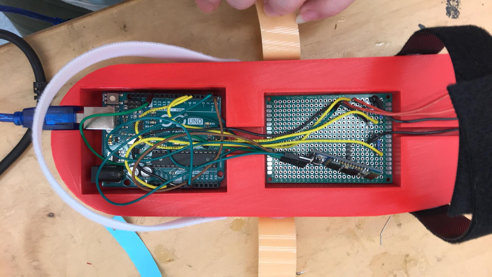
- Integration and refinement - Once the breadboard prototypes were all electrically sound, we moved on to putting together proto-board circuit for easier mechanical integration, making the electronics bay more compact, as well as lighter in weight in order to not cause hinderance in the walkability of the shoe. Additional to this, we started making schematics and designing a more formal electrical system. The hardware subteam came to a conclusion that it made a lot of sense to use a PCB to control the electronics - saving space, hardware mass, and adding redundancy to the system. We went through multiple phases of schematic reviews and PCB layout reviews with the teaching team, and shipped out a total of two iterations of two different designs of PCBs.
- Debugging and iterating - We spent the rest of the time strategically: About half of it was spent debugging, testing, and repeating and the rest of it was spent in discussions about safety, manufacturability, comfort, and daily usability of the shoe with stakeholders and faculty. This involved redesign and development of the electronics casing, the location of the electronics embedding, and some components for the printed circuit board, among others.
SCHEMATIC REVIEW
A description of the schematic iterations and PCB design
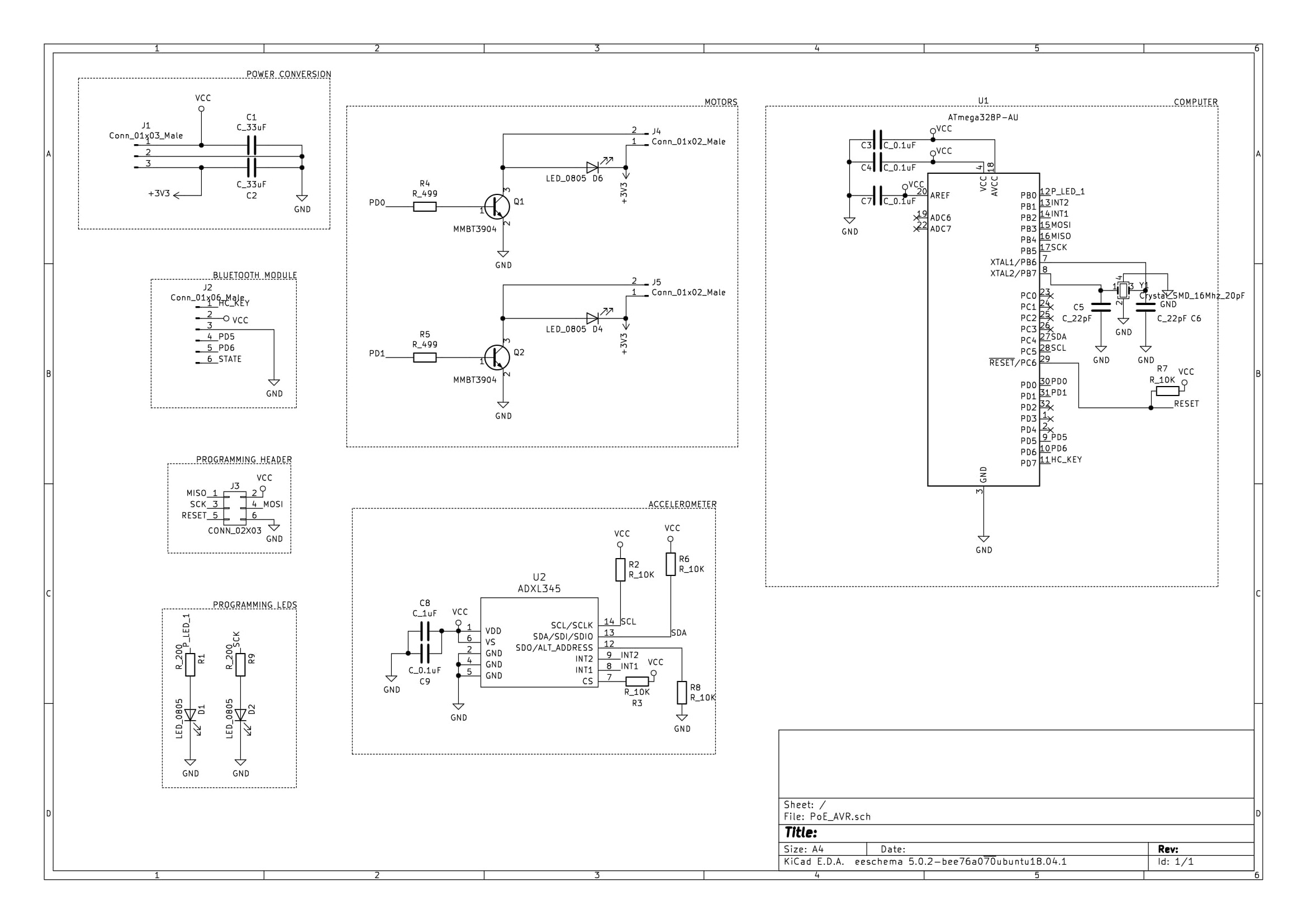
The main schematic includes the following sections:
- Power Conversion: We use a Lithium-ion battery input for the PCB at 3.7V. To step it up to 5V as required by some of the components on the PCB, including the HC-05 bluetooth module, we used a DC-DC Boost converter from Pololu.
- Bluetooth Module: We used the HC-05 bluetooth module to communicate to the PCB using a mobile application. All the power lines, as well as the I/O lines for this module are embedded in the PCB.
- Programming Header: Primarily used to program the microprocessor, and to power the board while in programming mode.
- Programming LEDs: Used as indicators to make the programming process easier to observe and test.
- Motors: A transducer that translates the electrical signals to vibratory motion for conveying direction information to the user in a handsfree manner.
- Accelerometer: For sensing the movement of the user to potentially measure activity data or motion-based commands.
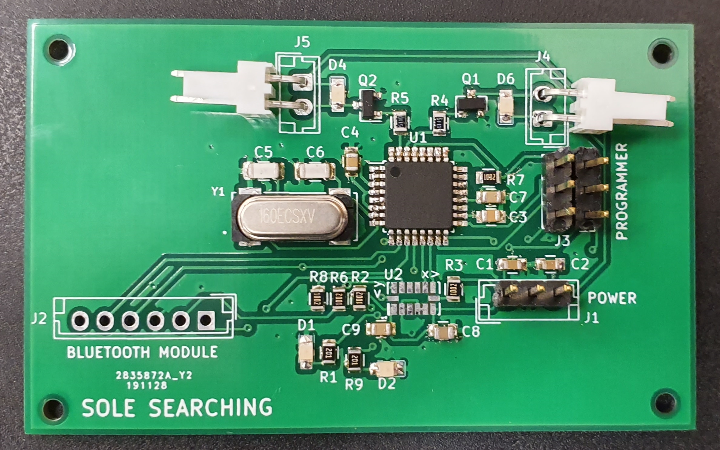
- Computer: We used an ATMEGA 328P-AU to process information from and to control I/O devices. We used an external clock operating at 16MHz, and used the digital I/O pins to communicate with the rest of the hardware.
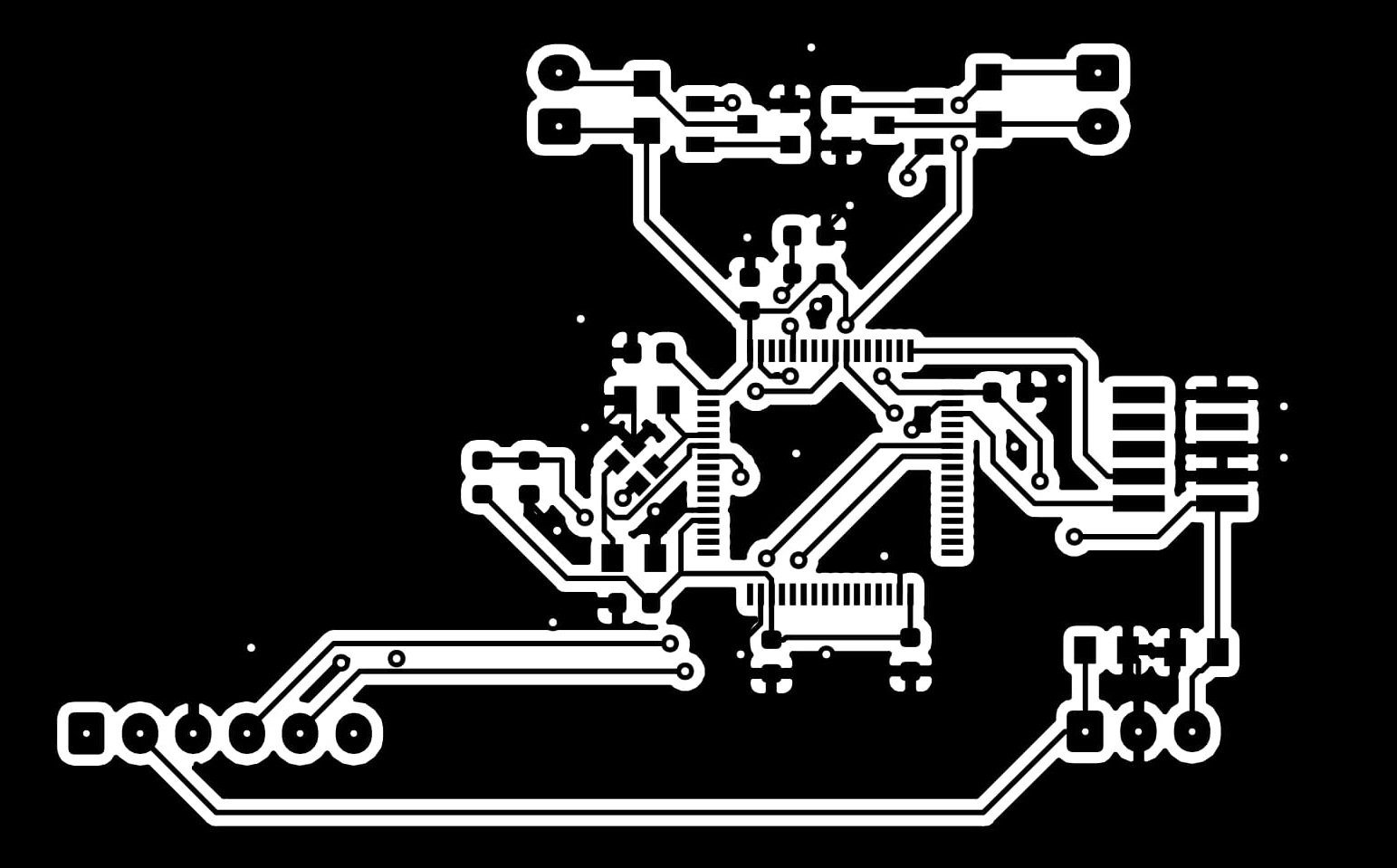
Here, we present the schematic for the electrical system.
| Part | References |
|---|---|
| Capacitor 0.1uF | C3 C4 C7 C9 |
| Capacitor 1uF | C8 |
| Capacitor 22uF | C5 C6 |
| Capacitor 33uF | C1 C2 |
| LED_0805 | D1 D2 D4 D6 |
| 1x2 Connector | J2 J3 |
| 1x3 Connector | J1 |
| 1x6 Connector | J5 |
| 40V 200mA NPN Transistor | Q1 Q2 |
| Resistor_499 | R4 R5 |
| Resistor_10k | R2 R3 R6 R7 R8 |
| Resistor_200 | R1 R9 |
| Accelerometer | U2 |
| ATmega328P-AU Microchip | U2 |
| Crystal Oscillator | Y1 |
POST FINAL SPRINT UPDATES
A brief description of the final electrical system updates.
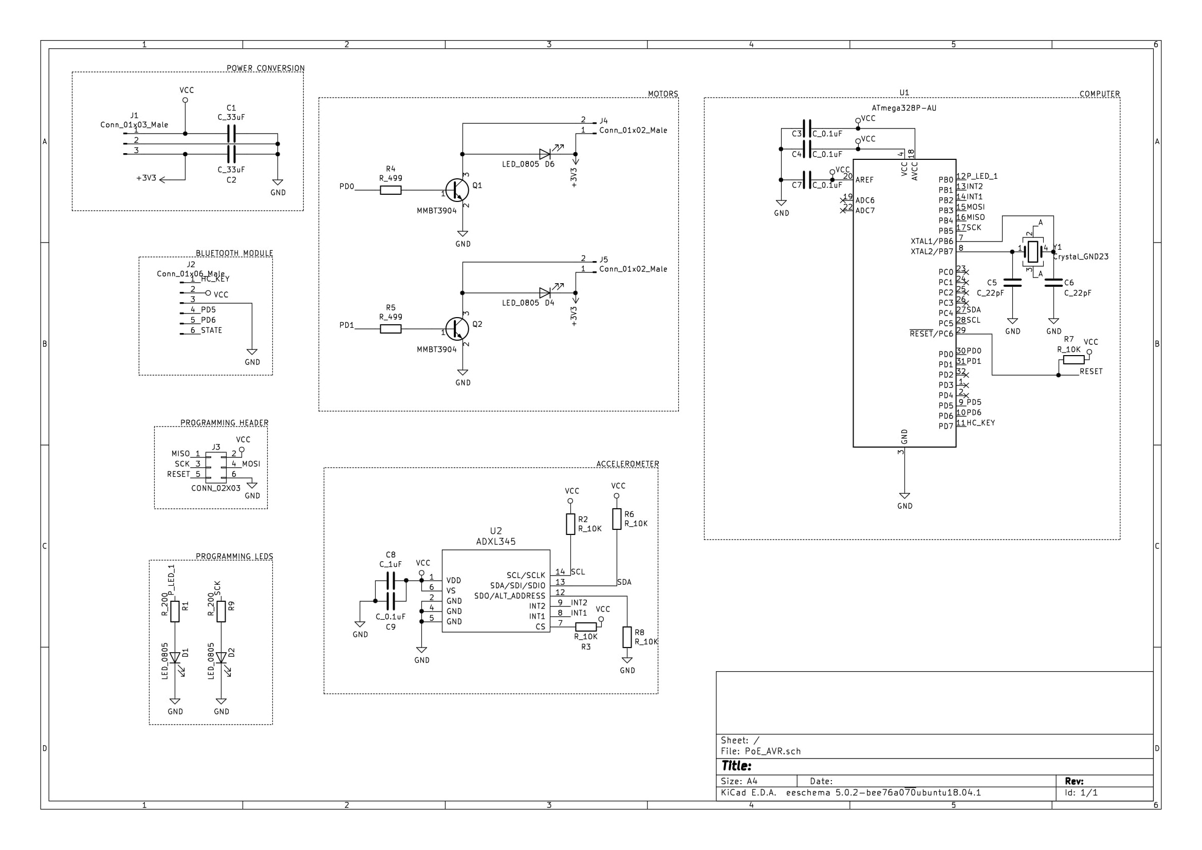
We passed the second iteration of the PCBs through more tests - both hardware and firmware. This includes compiling the program for the microcontroller and testing the supporting components to the microcontroller. Even though the board works well for our shoe system, we have made some final edits to the schematic. The most important edit was the correction in the integration of oscillator with the microcontroller.
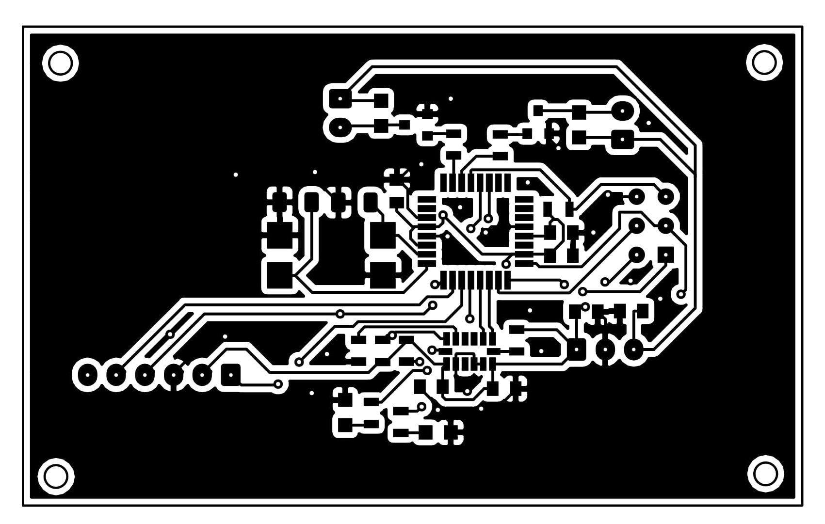
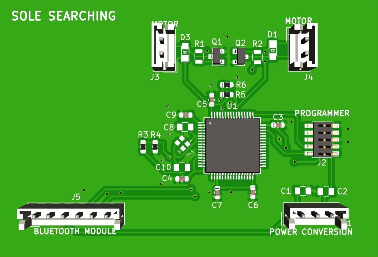
Here, we present the schematic for the updated electrical system.
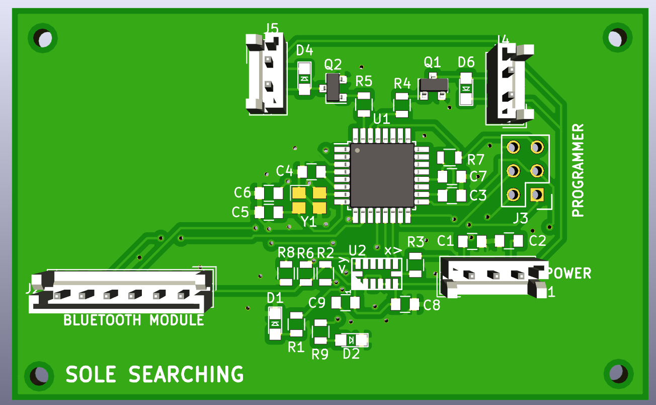
This image is a 3D rendering of the layout from the previous image.
CHALLENGES IN CIRCUIT DESIGN
- The size of the PCB was one of our biggest concerns. In order to fit our product onto a shoe and not hinder the normal walking, the PCB as well as the electronics case must appropriately designed. Thus, we decided to switch from using an Arduino Uno to an Arduino Nano, and finally to working on the chip level.
- We made some design errors in the integration of the external oscillator to the microcontroller. We debugged this error through Sprint 3 and post-sprint 3 and have updated the PCB and the schematic layout.
- Uploading the firmware to the microcontroller took a little bit of exploring the applications made by Atmel and the Arduino IDE.
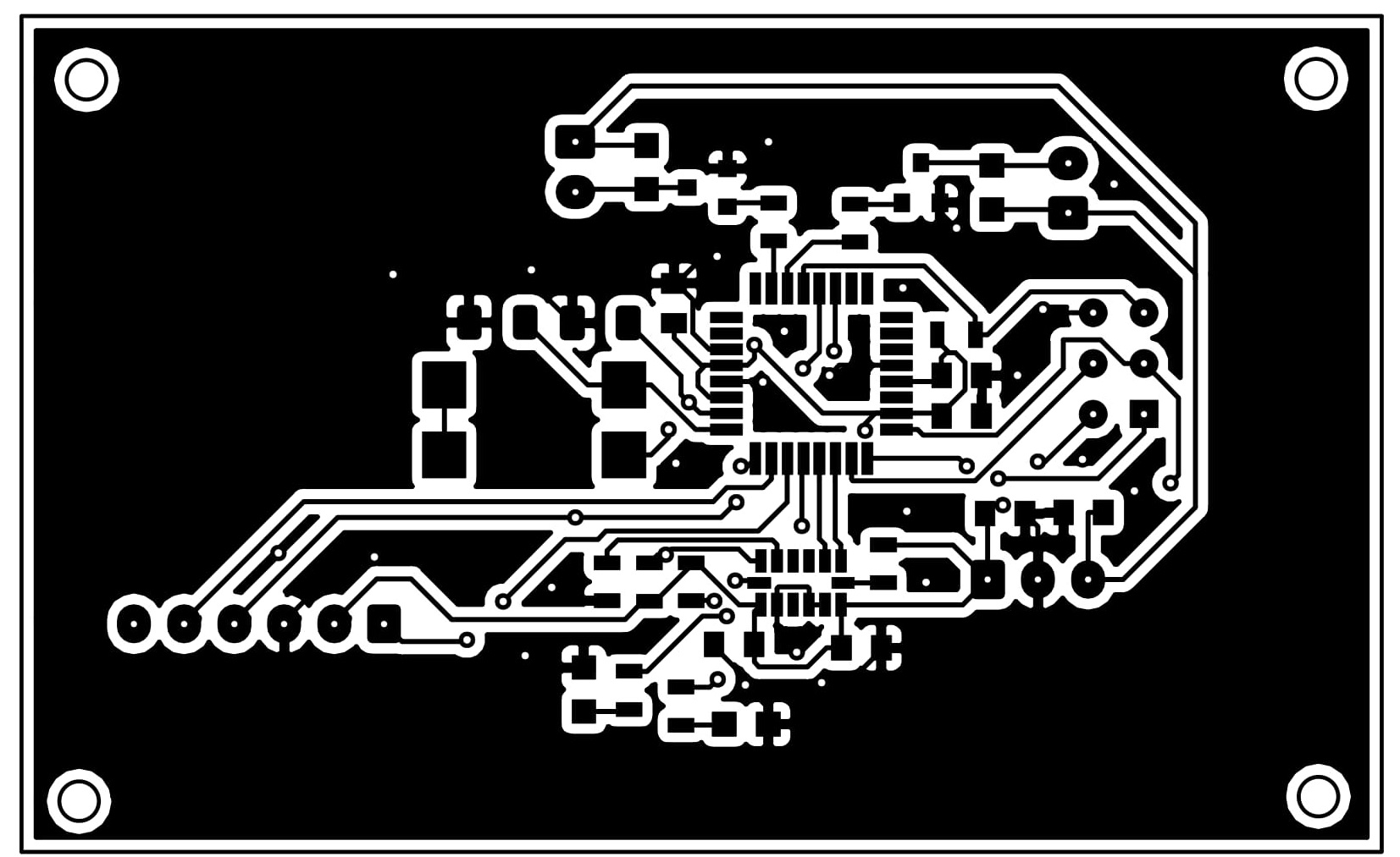
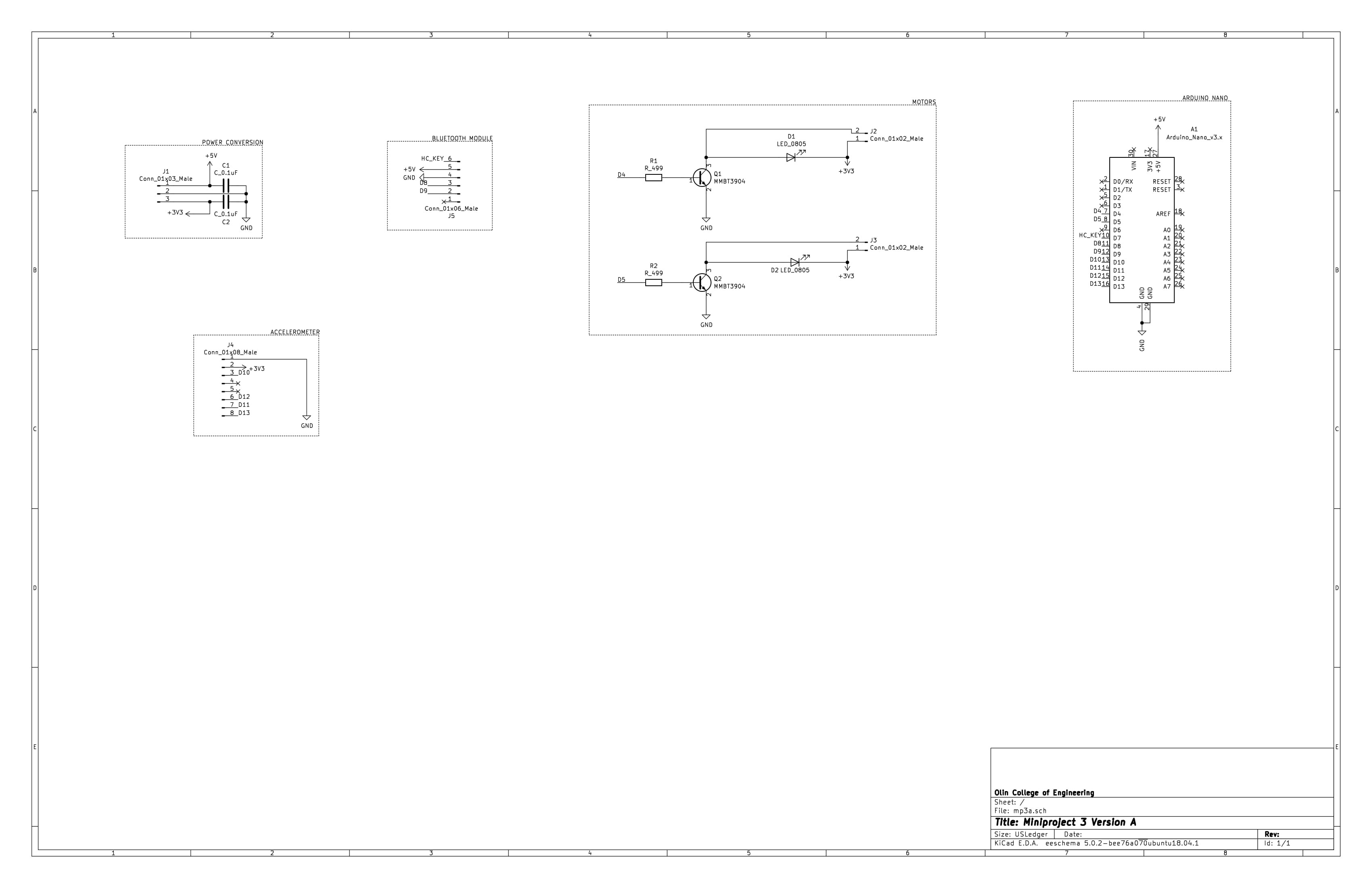
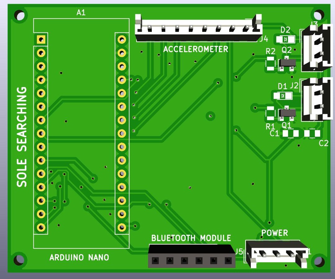
A MODULE BASED PCB
A brief description of the PCB with connectors for plugging in of the shelf electrical hardware.
In order to have a backup for the case if we were not able to upload the program to the microcontroller, we designed a simpler, module-based PCB. We use an arduino nano to communicate with the bluetooth module over software serial, and to control the motors.
Here, we present the schematic for the module based electrical system.
This image is a 3D rendering of the layout from the previous image.
The Bill of Materials for Arduino Nano board
| Part | References |
|---|---|
| Arduino Nano v3 | A1 |
| Capacitor_0.1 uF | C1 C2 |
| LED_0805 | D1 D2 |
| 1x2 Connector | J2 J3 |
| 1x3 Connector | J1 |
| 1x6 Connectors | J5 |
| 1x8 Connector | J4 |
| MMBT3904 | Q1 Q2 |
| Resistor_499 | R1 R2 |
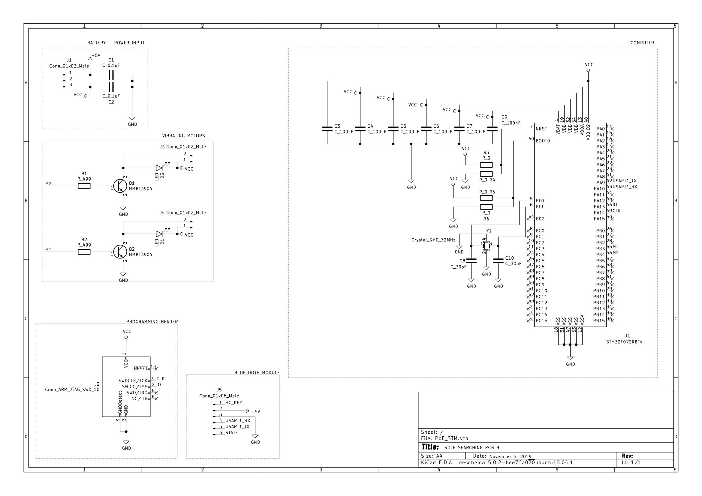
FUTURE ITERATIONS
What would be our next step if we had another sprint in this project?
We would explore the world of
- The degree of connectivity that the two types can offer. The STM32WB microcontrollers integrate an ultra-low power 2.4GHz radio supporting Bluetooth 5.0 and IEEE 802.15.4 wireless communication protocols. This simplifies the schematic by reducing the components and modules that we need, but makes the setup process more difficult due to the complexity of the processor.
- ARM microprocessors are designed to perform fewer types of commands, compared to the AVR microprocessors, so they can operate at a much higher speed, performing extra millions of instructions per second (MIPS).
- Differences in power consumption by each of the two types.
- Differences in pricing for each of the two types.
- Differences in the ease of programming and compiling codes for each of the two types.
- Popularity of use in the industry and commercial spaces.
Here, we present the schematic for the electrical system with an STM Architecture.
SAFETY AND REDUNDANCY
How do we ensure the safety and usability of our product?
- Safety is the first priority for our product. We used a 3.7V 1000 mAh rechargeable lithium battery for the power supply. The whole circuit board is driven by a 5V voltage, which is converted from the 3.3V from the battery using a voltage booster.
- A lithium-polymer battery can provide high specific energy than other lithium batteries and are used in applications where weight and volume are critical features, like mobile devices. They work well in a large range of temperature.
- We specifically chose a 3.7V 1000mAh battery that satisfies the need of keeping the smart shoe working for 2-3 days, which fits the need for daily need.
- According to the manufacturer, there's no deformation, rupture or leakage in the battery within the applicable temperature.
- The battery pack is attached to the shoe via velcro connection, which ensures a simple attach-remove mechanism as well as avoids a high pressure on the battery.
ELECTRICAL DESIGN REFLECTION
Thoughts on "what could we have done differently?"
In this project, the learning goal of electrical subteam is to practice designing and manufacturing PCBs. We approached a working PCB by several steps: first, we designed a breadboard circuit with an Arduino Uno, which provides every connection portal we need, including motors, Bluetooth module and other mall components. Second, we moved from breadboard to protoboard, which largely reduced the size of our product so that it can be placed on a shoe. Then we extend to making our own PCBs. We designed two versions of PCBs: for the first one, we used modulized components including an Arduino Nano and the Bluetooth module. For the second one, the design of PCB starts from chip level. We selected a microprocessor and build up te rest of the circuit accordingly. Our next step of extending our project into a real product is to create circuit protection. By potting the circuit we prevent moisture and inner circuit shortage. We would unify the voltage across the board to be 3.3V: both the motors and the bluetooth main chip run on 3.3V, and the LiPo battery provides a constant potential difference of 3.3V as well. By doing so we can eliminate the voltage booster and make our product even smaller. We would also change from molex connection to a permanent, soldered connection to avoid broken circuit between the motors and the main PCB.