Electrical Subsystem
Our electrical subsystem primarily consists of components that we used to power our high-current motors for the shooter, voltage regulators to power all of our logic components, and components to power our audio subsystem.
Powering High-powered Motors
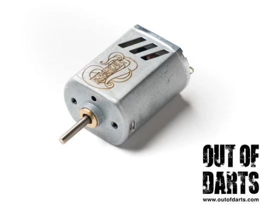
In order to make a more powerful shooter, we wanted to include motors that had a higher RPM and stall torque, but in order to do this we needed to find another way to power them since the motor shield could only support motors up to 1A but our new motors could draw up to 30A. Our solution to this problem was to purchase MOSFET boards which could support this higher current draw and added extra wiring to connect them to the Arduino for signal and the lipo for power.
Powering Logic Components
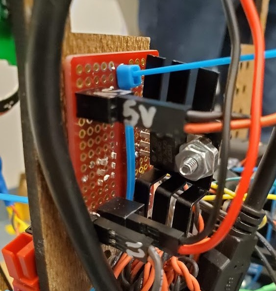
Our logic components - namely the Arduino, Euclid and Pi - required 5 volts to run properly. The voltage regulators we had on hand could support 5V at 3A, but since these components combined drew more than 3A, we needed to include several 5V regulators to sufficiently power all of these components. The LED ring light and the servo both also needed 5 volts but would brown out the Arduino if we tried to power them off the Arduino, so we included another regulator for those components as well. During our project, we ran into issues where these regulators would overheat and output less than 5V causing our components to shut down, so we needed to add fans and heatsinks to actively cool these components down.
Audio System
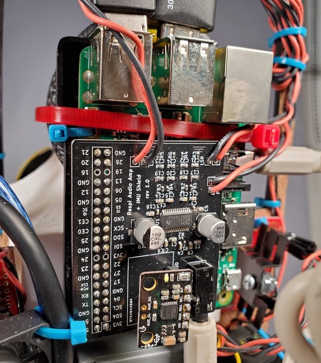
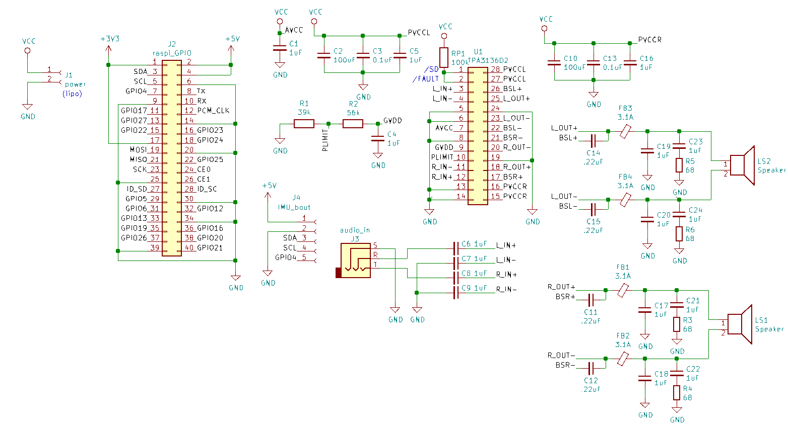
We figured that if we fully wanted to capture the character of the sentry turret that inspired our project, we were going to need to give it a voice. We were initially planning on running the audio setup off of a raspberry pi with software for speech recognition and audio playback from a database of voice lines from the game. We soon found, however, that the pi did not have anywhere near the power capacity to run our 2x 10W @ 8 Ohm stereo speakers, so we went back to the drawing board and started designing a breakout shield to house an audio amp as well as an IMU that gave the turret perception of when he was falling over so he could cry out in agony. The shield was fabricated on PCB with the IMU interfacing over SPI and a 3.5mm stereo audio interface to a TPA3136 stereo amplifier IC with filtering on the output to eliminate any significant noise over our direct line to the speakers.
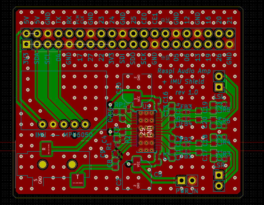
Due to the small size of the surface mount components, precision fabrication techniques were needed to assemble the PCB. Working under a microscope, an exacto was used to paint solder paste on to the pads. Components were also placed under the microscope using tweezers. The PCB was then cooked in the reflow oven to solidify the connections, and all the connections were tested with a multimeter to assure the reflow went as intended and nothing shorted unintentionally.
Audio Schematic
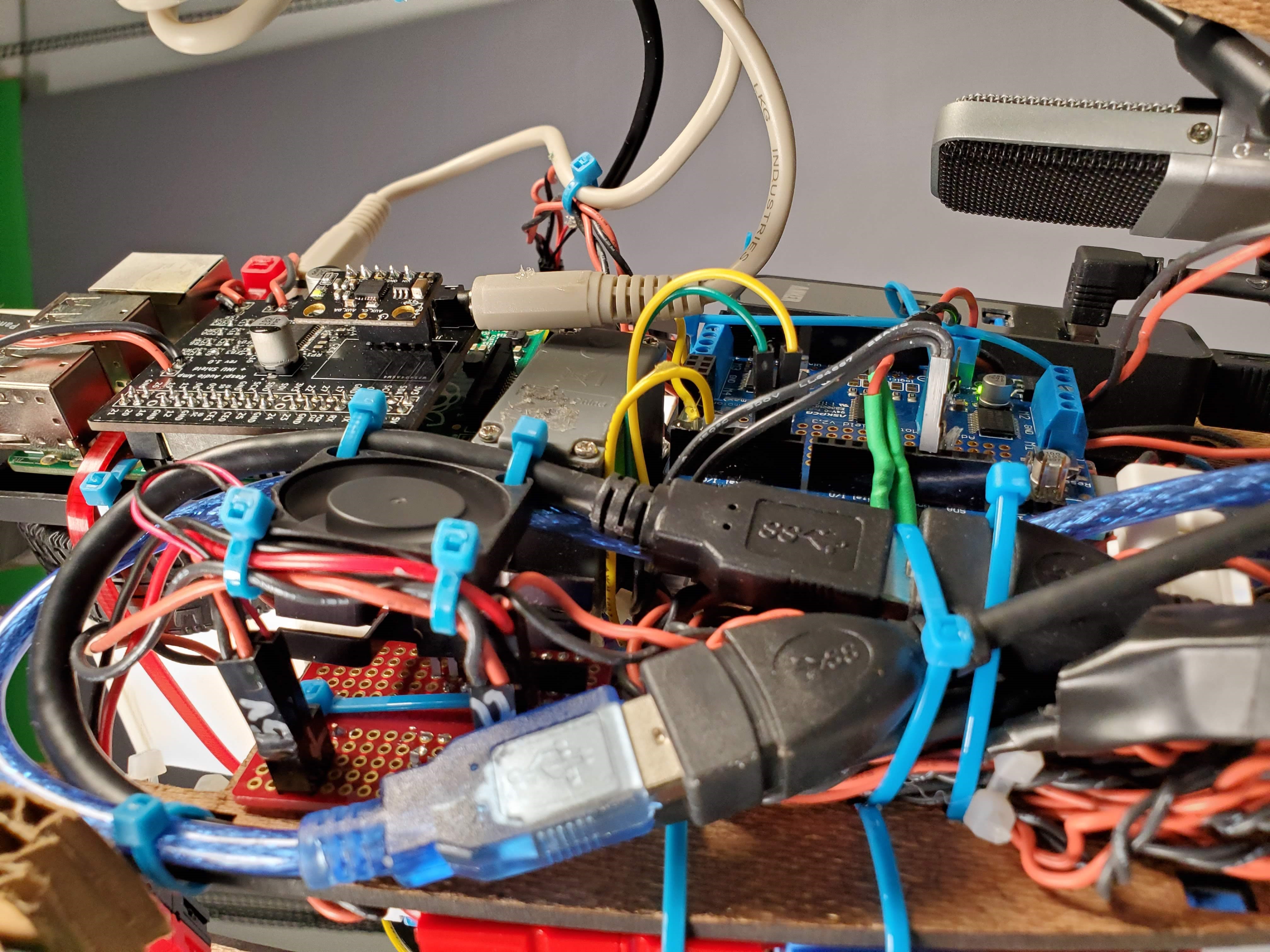
Full Electrical System
.jpg)