Mechanical Breakdown
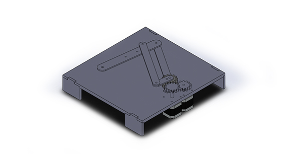
Arm CAD
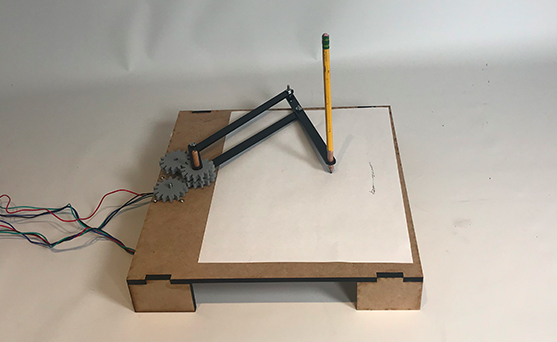
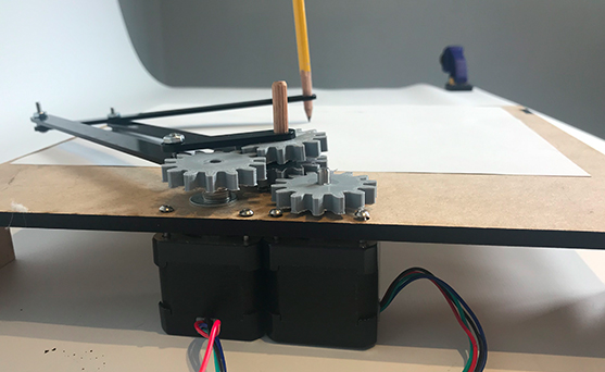
For sprint two, we settled on incorporating a gear drive, rather than a belt drive. The reason for that was time and cost - we could 3D print gears, and that was a quicker way to test our concept than buying a belt. We also scrapped the original arm design and instead made a four-bar linkage that was driven by two stepper motors. This system performed fairly well! There were still issues regarding weight - one of the linkages was weighed down enough that it dragged across the paper. But the dragging linkage looked a lot like a human elbow, and made the robot look more personable. Still, we knew we’d have to address the issue with that friction for the next sprint. Another issue was that our stepper motor shafts were not long enough for the gear drive. This contributed to gears skipping and not fitting with one another as well as they should.
Designing Table and Character
For this sprint we decided to not focus on the aesthetics of the robot since we were trying a completely new design. Our goal was to get our mechanism to move and have basic code integrated into it.
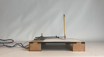
One of the issues that we ran into with this table design was that the table was too small and the pencil kept falling off the edges. We are trying to find new ways to improve the system.
Electrical Breakdown

For the second sprint, we decided to transition to servo motors. The reasons for this were simple - we decided that we wanted a system that was more precise than servo motors could provide. We also worked on this sprint on integrating with the mechanical system a lot earlier on. As a result, we had the motors powering a gear drive that then powered the arm.
This sprint was a major learning experience, as none of us had any experience with stepper motors, so we worked with the teaching team to learn more about them, and wire them up. The end system used an Arduino, motor shield, motor drivers, and the two motors, as well as a laptop charger we adapted into our power supply.
After this, we decided to shift our focus on improving the mechanical and software systems, as we needed to work more on integrating the two. So our Sprint 2 adaptation for the electrical system was the final adaptation.
Software Breakdown
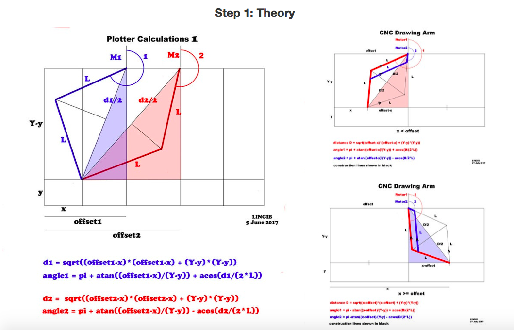
For sprint two, we took our broad research and focused on what we could actually implement. This involved scripts of scrap code from an online source where we gained inspiration for the design of our arm, and Stan’s speedy stepper library. We took crucial steps to understand the existing code written and learned about how they integrated their mechanical setup with the code. Unfortunately, this code was terribly written and this made it difficult to find out how they created their X-Y coordinate system and implemented their kinematics. The only information we ended up using from the code was the kinematics equations they derived for a four-bar linkage. With that being said, we did not implement code on time for our Sprint Review, but we did implement it after.
Visit our Github to get access to our code and see the progress we had made.
Bugdet Overview
| Expenses | Comments | Sprint | Price |
| Acrylic | 12" x 12" x 1/8" | Second | $7.14 |
| Sheet Metal | 12" x 12" x 0.016" | Second | $8.83 |
| Stepper Motor | Bought Two ($12.99 each) | Second | $26.98 |
| Power Supply | --- | Second | $13.99 |
| Motor Shield/Driver | --- | Second | $19.99 |
| Total: | $76.93 |
Not including shipping