Overview
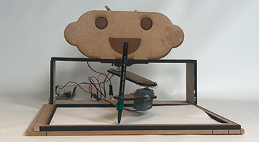
In Sprint One, Andrew was made of MDF, Hardboard and 2 Servo Motors. The servos were too heavy for the mechanism which made the arm a bit difficult to move. In this iteration, code was not implemented, but there was a lot of research going on backstage.


Mechanical Breakdown
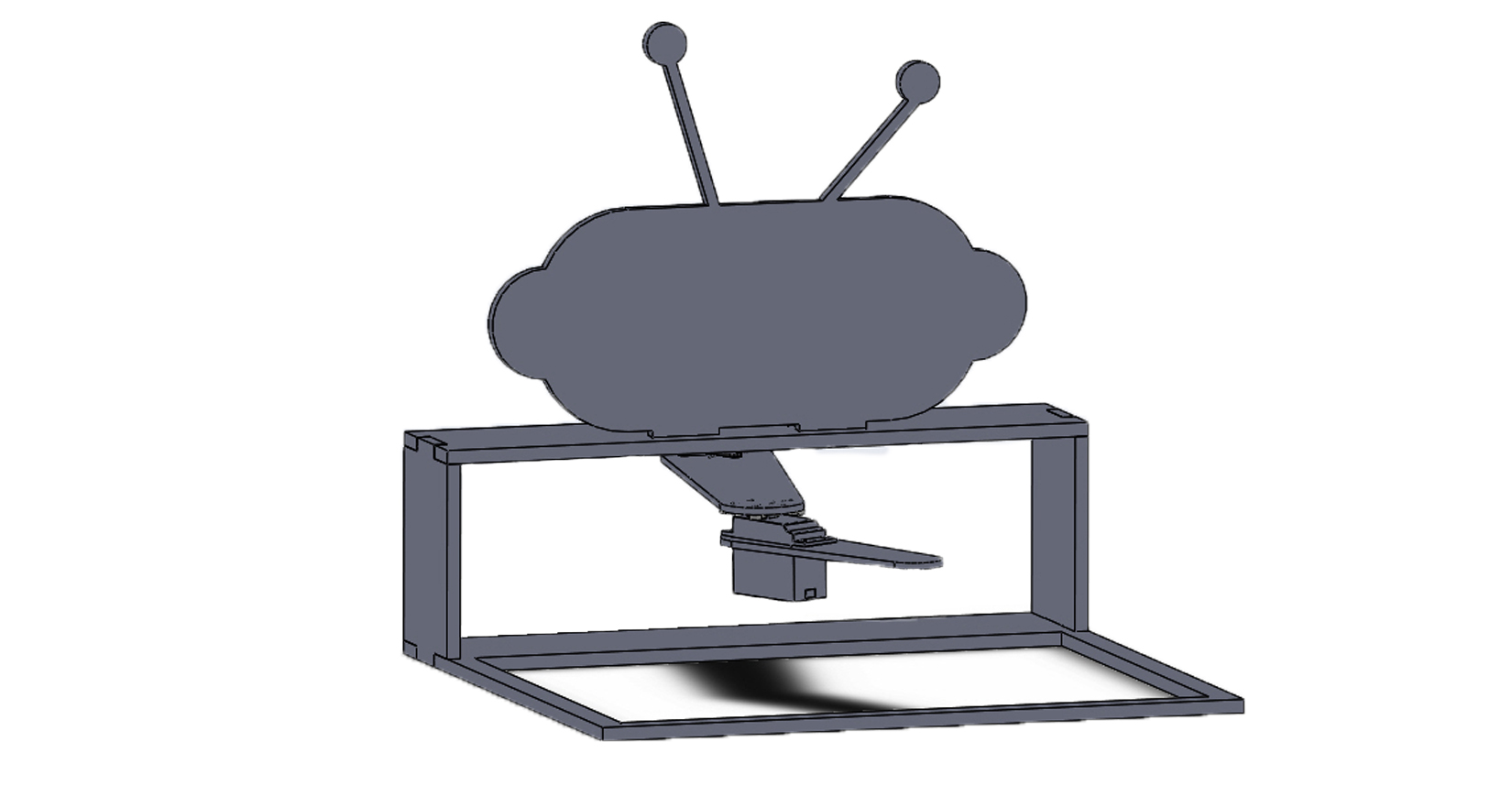
Arm CAD
In sprint one, we tentatively decided to go with a drawing arm rather than a CNC drawing system. We wanted to see if two joints would give us the mobility we desired for it, so the first sprint’s system was all about testing out that theory. The way it works is that there is a servo motor controlling the “shoulder” joint, and another directly controlling the “elbow”. We also restricted the page size with a tray, made by laser cutting two layers of hardboard and layering them. The tray restricted the potential different paper sizes we wanted to incorporate, so we decided we could do without it. The issue with the arm was the “elbow”. The servo motor weighed down the system. Because of that, we knew the second sprint needed to incorporate a gear or belt drive.
Designing Table and Character
We wanted to create a robot that was approachable, cute, and personified. At first we were debating about whether or not make it look like an animal or give it an creative theme (i.e. marine theme, space theme, etc.). After various iterations, we decided it would be best if we continued to emphasize the fact that it is an approachable robot by giving it an adorable robot head.
Electrical Breakdown
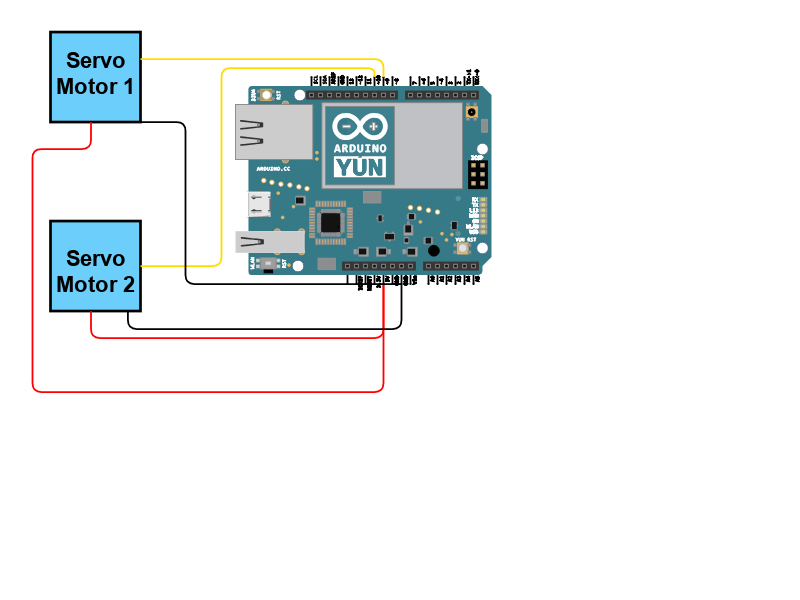
For the first sprint, we used two servo motors to power the arm. We used these mostly to test the motion we wanted, as they were easily available to us. We connected them to an Arduino, and powered the whole system through our laptops.
This worked decently well for our first iteration - it showed us how we could move the arm similar to the joints of a shoulder and elbow. However, the integration with the mechanical design was still lacking, which meant that our servos directly powered the rotation of the arm, without any gears or a belt drive. The second motor weighed down the arm, proving to us that we needed to integrate the mechanical and electrical components more carefully.
Another issue with this first iteration is that we were looking for a certain degree of accuracy of the arm, which servos couldn’t provide. We knew that for the next sprint, we’d need to look into updating our electrical system.
Software Breakdown
The first sprint for the software side of the project consisted mostly of research. Most of us being very new to programming, we needed to get an in-depth understanding of the tools and concepts that were available to us, and how we could use them. Here is a brief overview of what we researched:
1. Inverse and Forwards Kinematics:
- Learned how to solve for the kinematics of a 2DOF arm
- Found libraries that solved them and connected to servo motors like Tinyik Python Library and Arduino IK Library
2. UART:
- Researched how we could transfer bytes, and at what rate, between python, and arduino without overloading the arduino with motor commands
3. Single Line-drawing Algorithms:
- Sample code that could draw arms with servo motors
4. Open CV and the Canny Algorithm:
- Explored the library and its different functions
- Learned about the Canny algorithm that outlines images
5. Vectorising Images:
- Learned about some image vectorizing algorithms
- Aimed to use it to turn outline image into plottable and drawable equations
Bugdet Overview
| Expenses | Comments | Sprint | Price |
| Fiberboard | --- | First | Free |
| Servos | x2 | First | Free |
| Total: | $0.00 |