The mechanical system is the main component of our Pandora project.
The entire system is made of several subsystems.
Mechanical Enclosure
First Iteration
|

|
Second Iteration
|
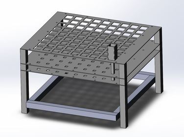
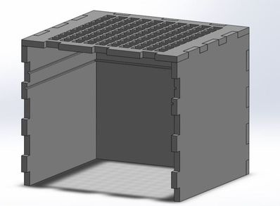
Fabrication:
In the first iteration, we fabricated the plate using a shopbot. After evaluating the design, we decided to reduce the size of the enclosure so the plates could be laser cut. This allowed for more precision in machining and speed of fabrication. The second iteration's sides were constructed using the shopbot and a circular saw to create the channels in the sides.
In the first iteration, we fabricated the plate using a shopbot. After evaluating the design, we decided to reduce the size of the enclosure so the plates could be laser cut. This allowed for more precision in machining and speed of fabrication. The second iteration's sides were constructed using the shopbot and a circular saw to create the channels in the sides.
|
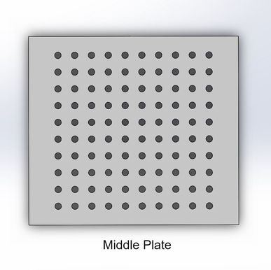
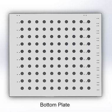
The middle plate and the bottom plate go into the channels of the box to provide additional supports for the blocks. There is spacing between the two plates. This is where the locking mechanism resides.
|
|
|
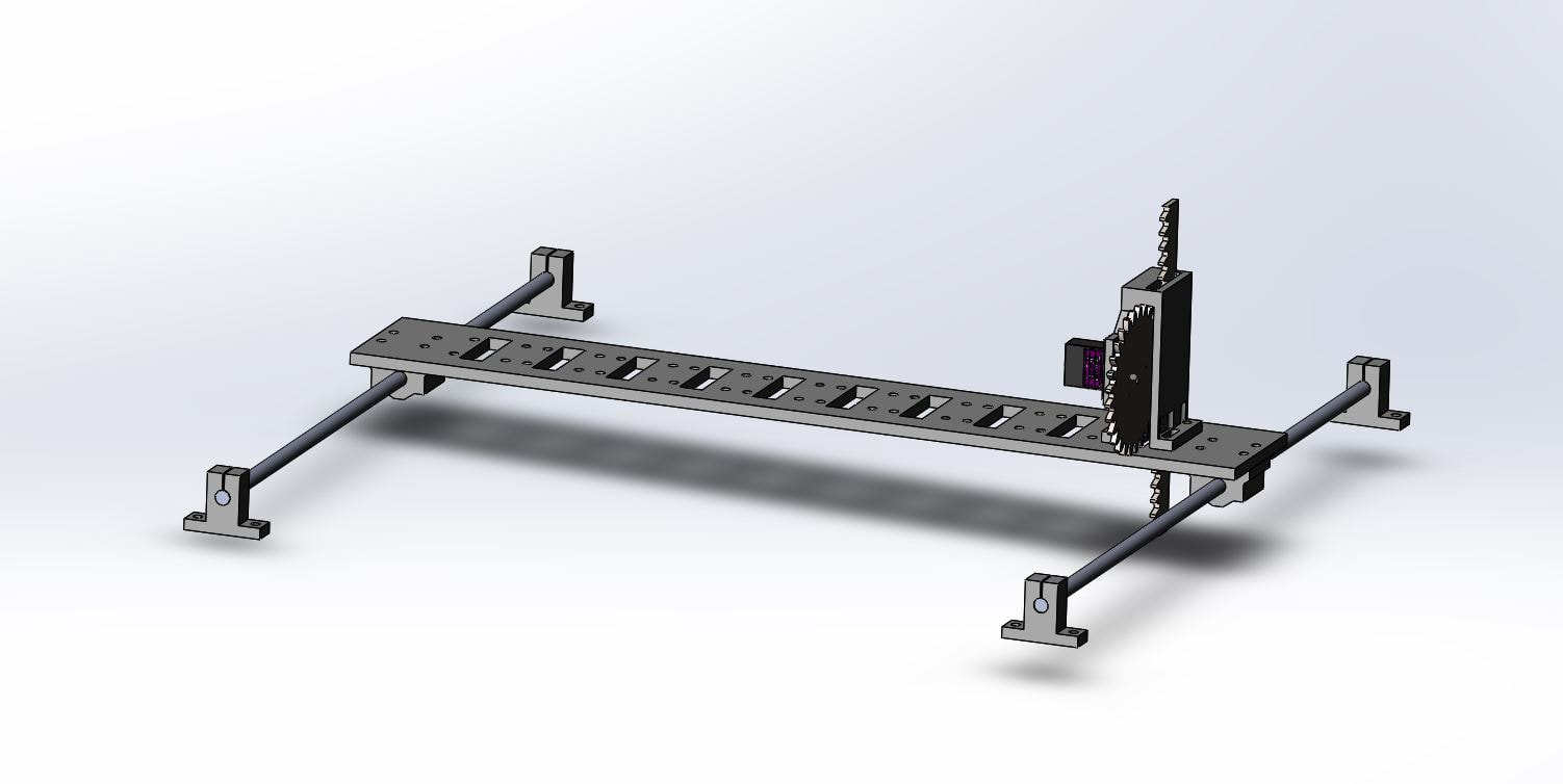
The Gantry System
Due to our budget constraint, our team could not buy 100 individual actuators for all 100 prisms. To be more cost efficient, our team came up with the solution to have a belt gantry system that has 10 actuators attached in a row to push all the prisms on each row to designated heights, and then lock the row with our locking mechanism. The gantry system then moves on to the next row. |
|
|
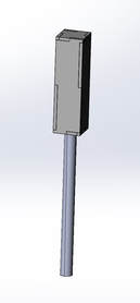
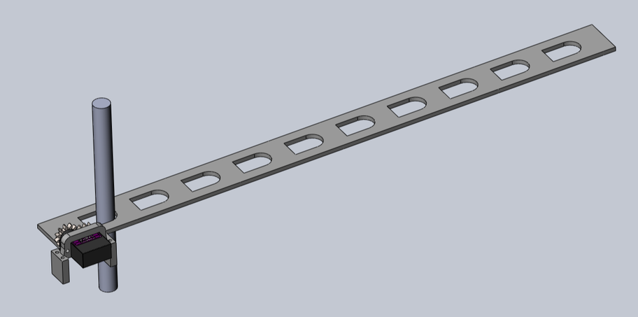
Actuators X 10
On top of the gantry plate, there are 10 actuators that will push the prisms on each row to respective depth data sent from the X-Box Kinect sensor. Each actuator sub-system is made of a rack and pinion with a custom made sliding guard to keep the movement linear. 
|
|
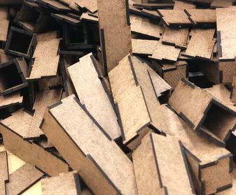
Prisms X 100
Our prism is made of 6-sided laser cut hardboard pieces and one 6 inch long wooden dowel. Our team has spent countless hours on the manual labor to put all 600 laser cut pieces together. |
|
|
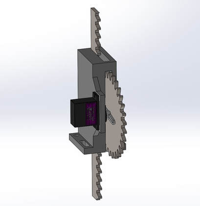
Locking Mechanism
|
|
The locking mechanism works by utilizing friction to keep the dowels in place. The plate has a felt material on it that interacts with sandpaper of the dowels to create a friction hold of the dowels at the correct height. We are using a rack and pinion to translate the plates linearly.
|
If you are interested in the SolidWorks files to recreate this project, go take a look on our GrabCAD.
Don't forget to shoot us an email with a picture of the final product though.