Mechanical Design
Sphere.
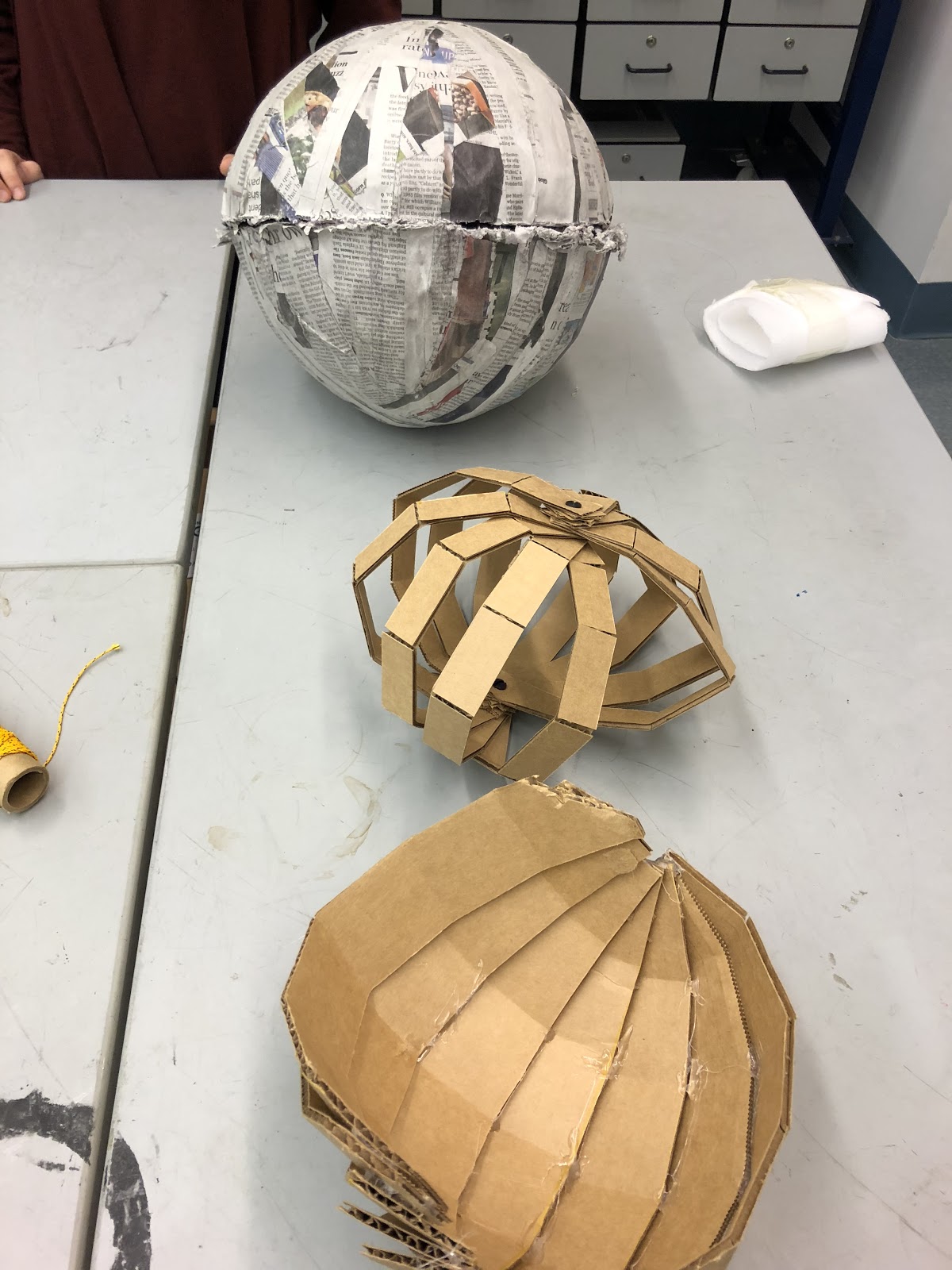
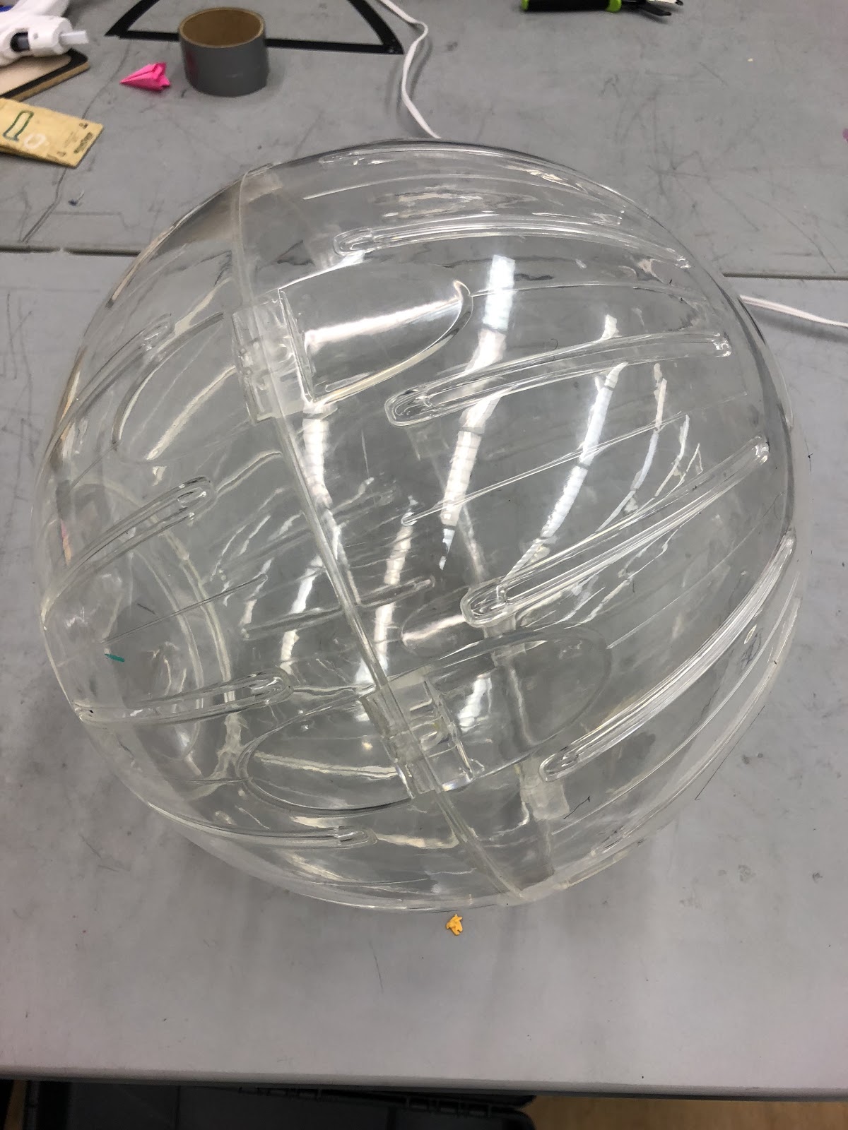
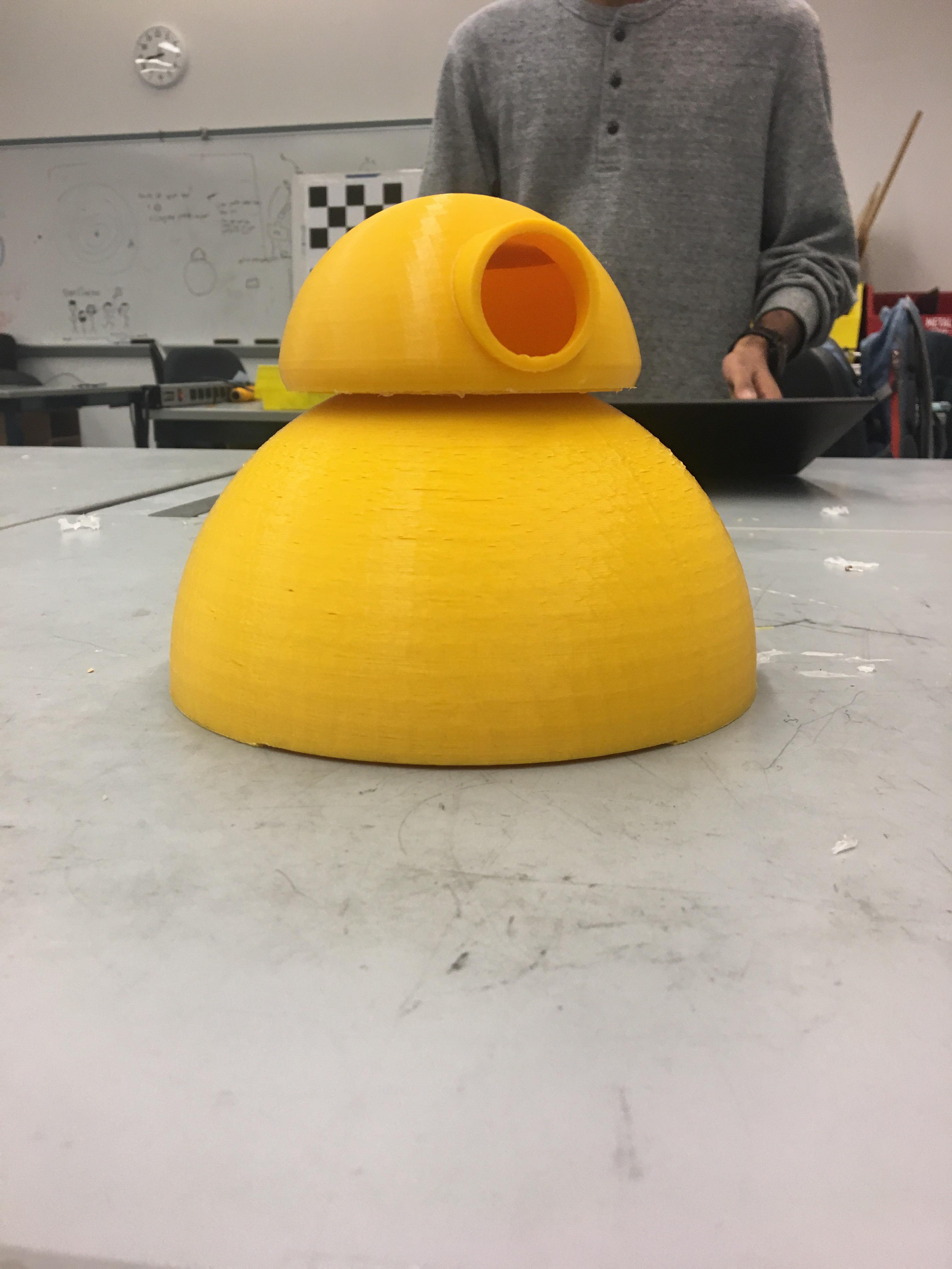
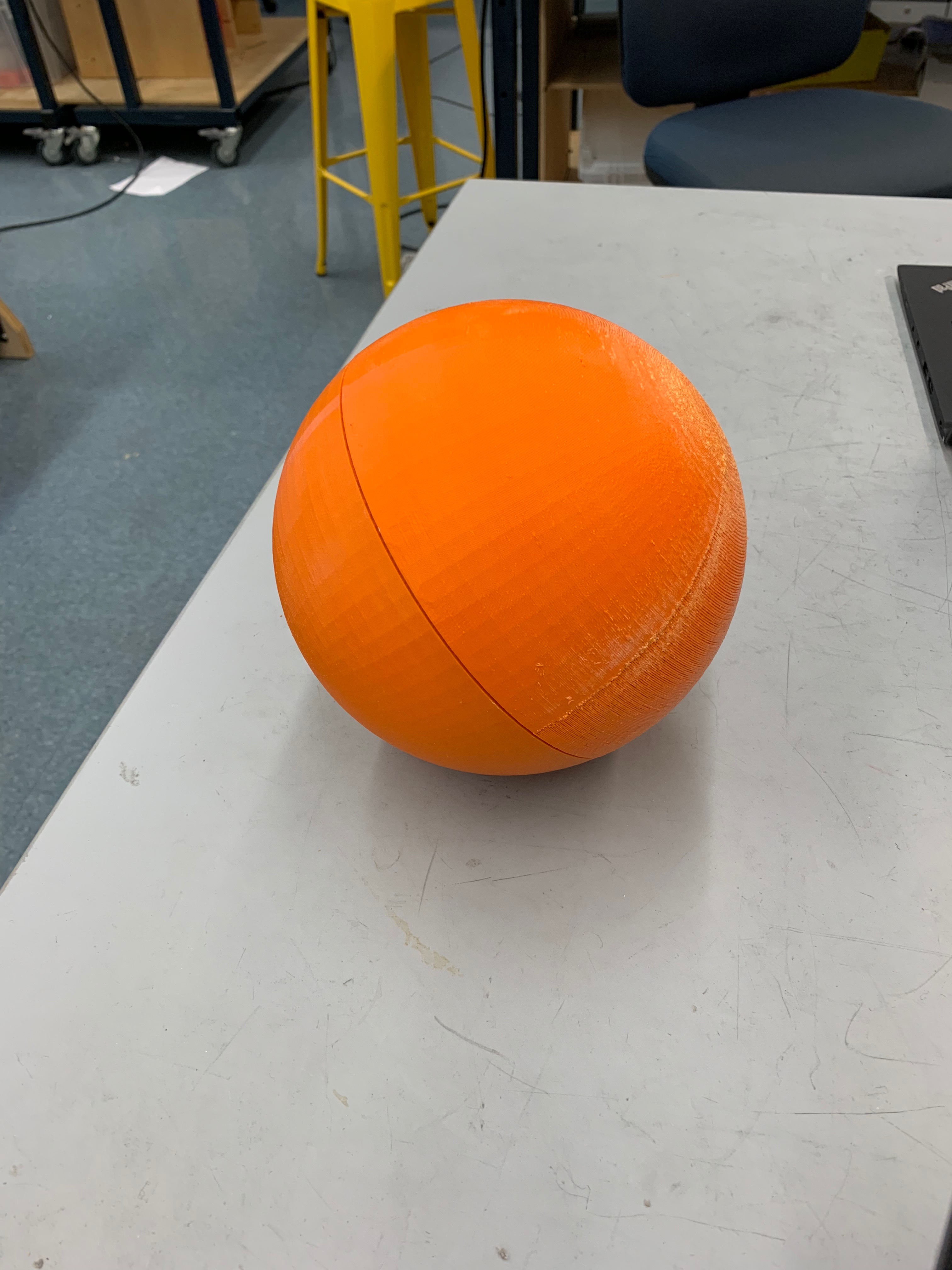
In the progression of images above, you can see how we started prototyping with paper-mache, and then worked with a hamster ball, then a small 3D printed sphere, then a larger acetone smoothed 3D printed sphere.
The creation of the sphere was definitely our biggest mechanical challenge, as we needed it to be smooth on the inside and outside in order for the ball to roll consistently. We ended up 3D printing two hemispheres on the Stratasys printers in the Robotics lab at Olin College. We chose this option because it was the most effective way to create a consistent sphere that also came together in a way that we determined. We decided to use a press-fit mechanism to seal the sphere.
After printing the final sphere, we sanded down the inside and outside of the sphere with 150 grit sandpaper, and performed acetone vapor smoothing in order to achieve the smoothest surface possible. The acetone vapor smoothing was done using sponges soaked in over the counter nail polish and placed underneath the hemisphere turned upside down for about 5 hours.
In order to connect the two sides of the sphere, we used a press-fit mechanism so that we could press them together and the overlap between the two edges would hold it together. This allowed us to easily open and close the sphere while having a smooth surface on both the inside and outside of the sphere.
Driving Mechanism.
After creating the sphere, the next challenge was creating the driving mechanism for the robot. We needed to ensure that the sphere could move in a consistent direction. This was harder than we initially thought.
For our driving mechanism, we have a mount inside of the sphere that has two wheels and roller bearings on each side so that the inside mount is able to move around freely within the sphere so that when the wheels spin, the only friction is because of the wheels motion relative to the inside of the sphere.
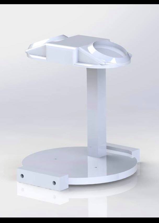
In these progression of images, we first have the CAD render of the final 3D printed mount that we used. At the top of the mount are two slots for the magnets to lie so that they're pressed against the inside surface of the sphere. The two blocks at the front and back of the base are so that we can mount the transfer ball bearings, as seen in the 3rd and 4th image.
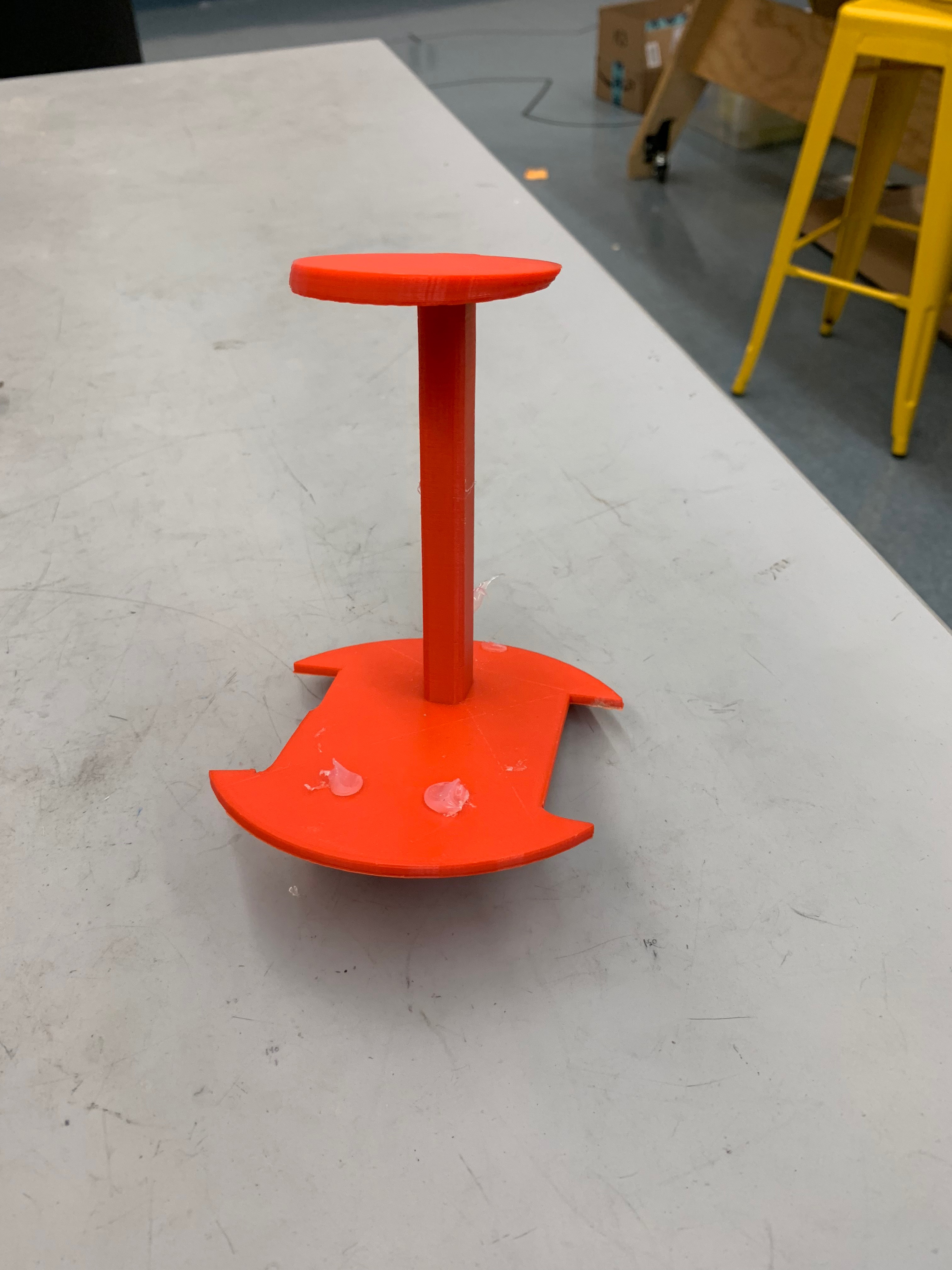
The second image was the first iteration of our internal mount, and although it wasn't used for the final iteration of our internal mount, it was helpful in deciding the orientaiton of the wheels and the position of the magnets on the top.
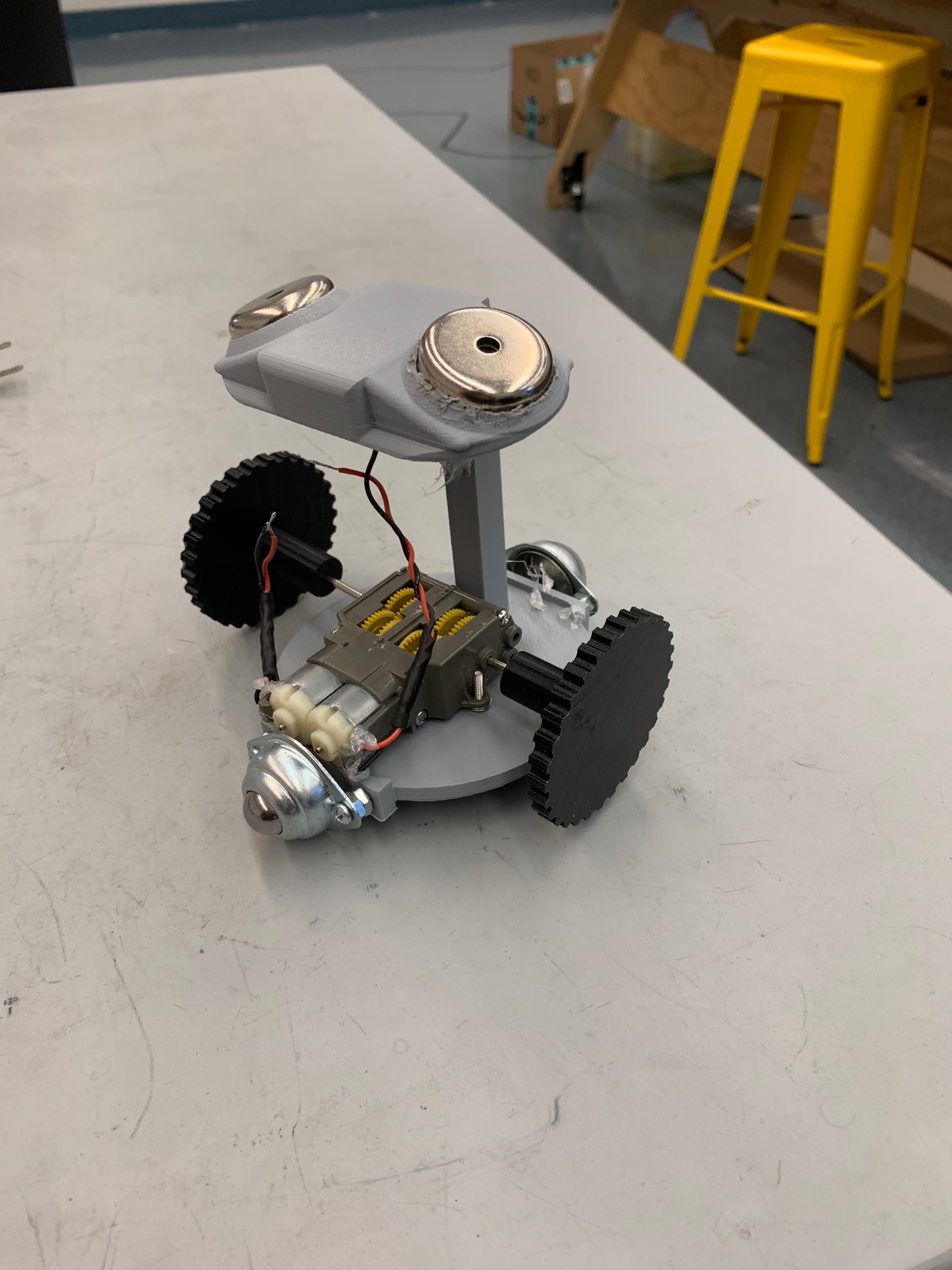
In the third image you can see the motors that we used to power the wheels and the gears that allowed us to have a gear ratio of 203:1. This allowed us to apply small amounts of energy and still have the wheels operate with large amounts of torque. Additionally in this image you can see that the tread of the wheels was just 3D printed ridges. This worked for testing but for our final version we needed a tread with more grip on the inside surface of the sphere.
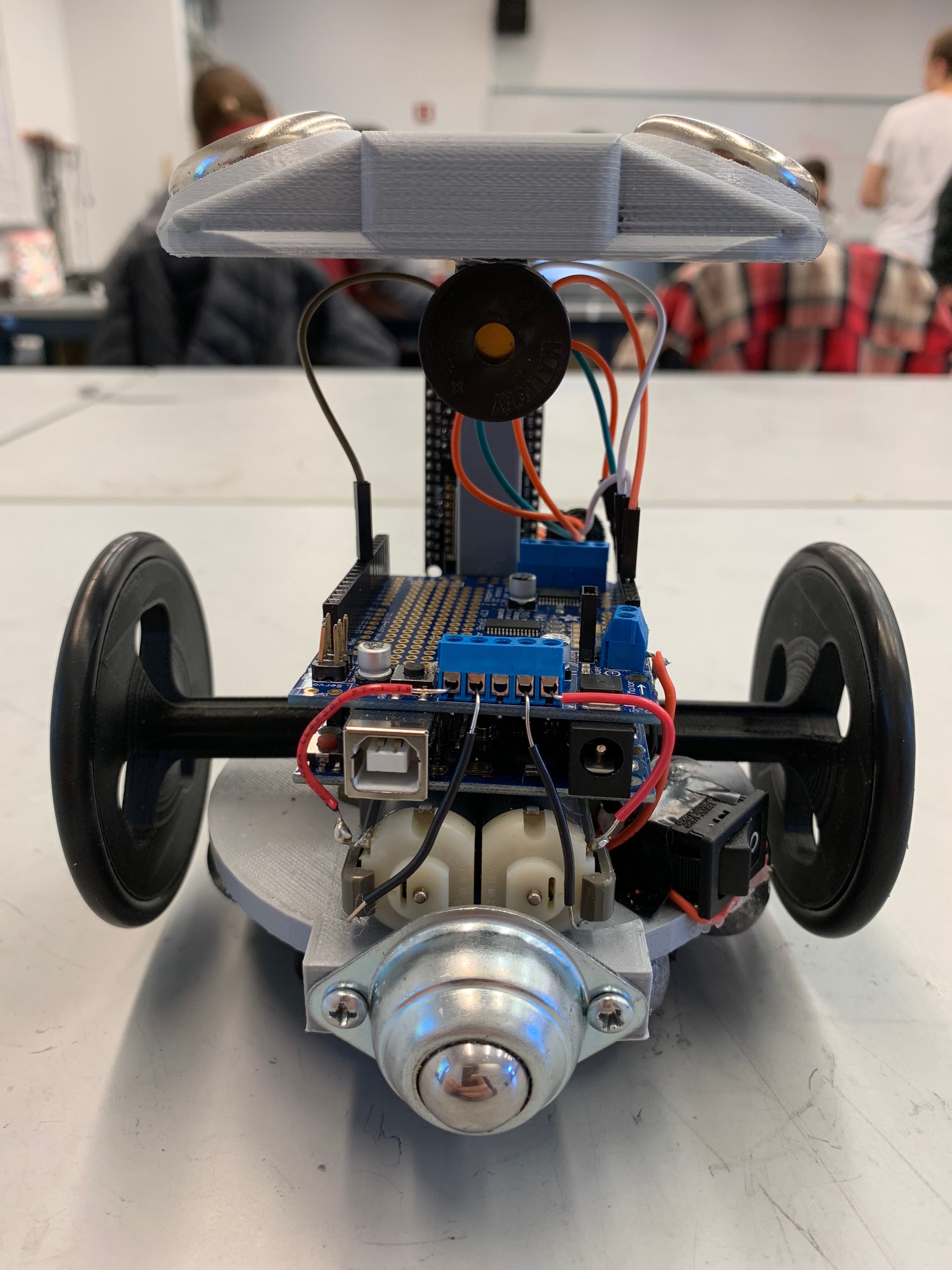
The fourth image in the sequence is the final interation of our inside mount. This iteration includes many more interesing features. For starters, the tread of the wheels is a large O-ring, which allows us better grip against the inside of the sphere. We have also mounted the arduino and motor shield that allows us to control the direction and speed of the motors. We mounted the 12V 2000mAh NiMH battery that powers the arduino, motor shield, and motors below the base of the 3D printed structure. Mounting the battery low is very desirable as it allows us to have a very low center of mass and thus keep the internal mechanism upright. One final feature that is included in the final iteration of the internal mechanism is the addition of a speaker (the small black circle just under the top part of the 3D printed structure).
Head.
One of the most challenging parts of this project was creating a head that could move independently of the sphere, and stay on top as the sphere rolled around. The way that we went about doing this is by using magnets on the inside of the sphere and magnets in the head so that the head was always aligned with the orientation of the inside mechanism of the sphere.
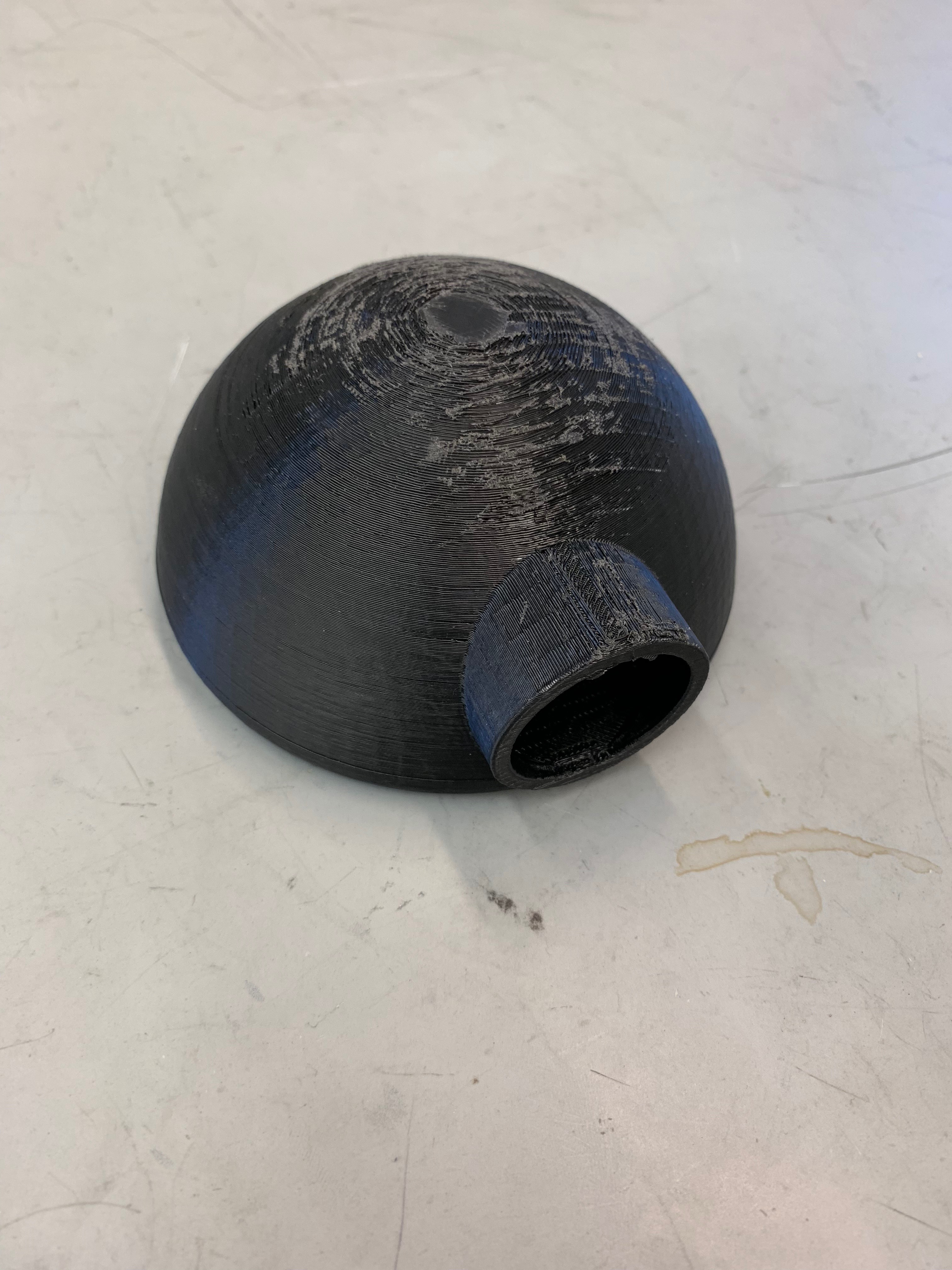
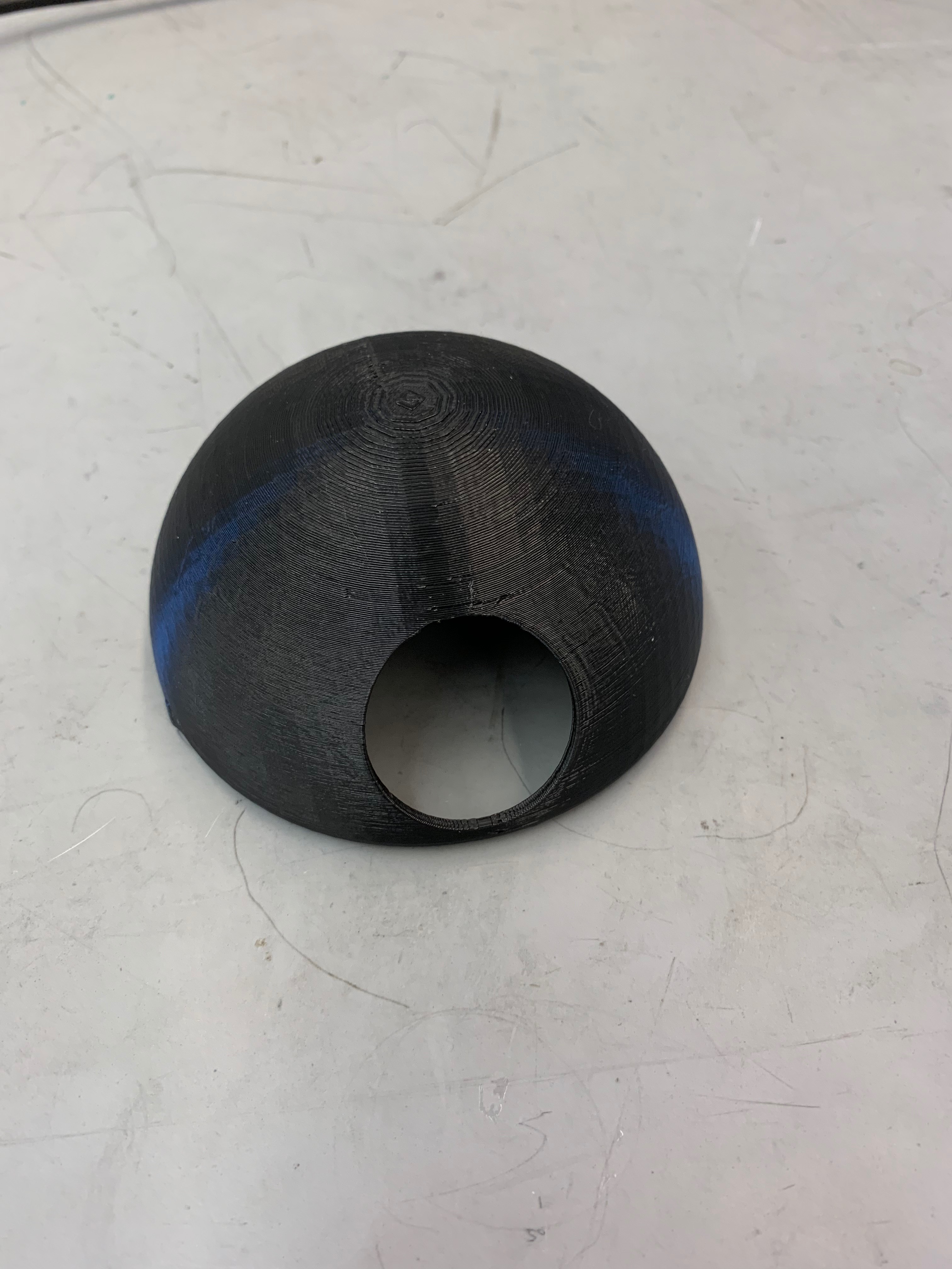
The two images in this section show the two iterations of the head for our robot the image on the left shows the first iteration, with a tubular eye-hole for the camera. One of the greater challenges with the head was making it as light as possible. Thus, in the second iteration, we removed the tubular eye-hole, and made the head as thin as possible. Additionally, because of the way we printed the second head, there was a much better finish that added to our whole aesthetic.
Although the mechanical aspect of the head was difficult, even more challenging was the electrical and software component. We needed to find a way to relay information from the camera in the head to the arduino inside the sphere so that we could send wheel speed commands.
CAD.
https://drive.google.com/drive/folders/1s7FVSHTs0oLHdBJY_3x-t8XOMnYtySe3?fbclid=IwAR34h53mTd2ZxY_am6IILeh9JSiC8_-Yuo6IyeZHwrDvGhinKo8YgwLUNrE