Mechanical Development
a potpourri of plastic cups, tubes, valves, and ink. lots of ink.
Overview
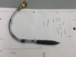
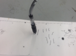
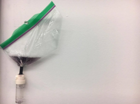
After passing through all the other stages of the pen, the ink reaches the pen tip. The pen tip was taken from a zebra v-301 fountain pen.
 >
>Design Process
Our choice of pen tip was based directly off of research into inks. We found three common ink types: oil based, alcohol based, and water based. We feared that alcohol based ink, what is found in many felt tipped pens, would evaporate too quickly and have a pungent smell. We also tested oil based ink and found it to be too viscous. We tested water based ink and found it to be slightly too viscous, but the addition of a small amount of detergent fixed this and did not negatively impact water quality. Water based inks are used primarily by fountain pens, and, because we did not know much about fountain pens, we bought a cheap one from amazon. We found that this pen worked quite well, and could be easily integrated into our system so we stuck with our initial pen choice.
Overview
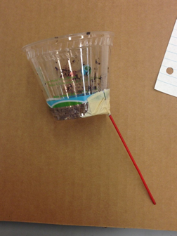
Pinc contains reservoirs of cyan, magenta, and yellow ink for drawing, and water for cleaning. The reservoirs each have a hole in the bottom that leads on to the IV drips. Because our system has no active pumping, the reservoirs are located at the top of the system to ensure that the ambient water pressure will allow the fluids to flow throughout the system.
Design Process
Our reservoirs had two very simple design requirements: they must be able to hold liquids without leaking, and we must be able to remove fluid from them when needed. These simple goals had a simple solution in the form of plastic cups. They can hold water indefinitely, only experiencing loss from evaporation which we did not worry about, and are easy to create a hole in to remove water. We made several iterations throughout to get plastics that were softer and easier to deform, but the core material choice never changed.
Overview
Pinc utilizes IV drips as the first step to control fluid flow. These drips, which are the same kind that could be found in a hospital, control the drip rate with a knob that allows more or less fluid to flow by constricting the tube by varying amounts. The IV drips control the flow rate of different fluids through our system.
Design Process
When it comes time to removing ink from the reservoir, not much is needed because a pen does not require a large amount of ink to write with. The flow does need to be smooth however, and preferably controlled. Our first attempts to remove ink from reservoirs involved using straws from air spray cans, but these proved to be so narrow that the surface tension of the ink prevented any flow. We then moved to 1/8” ID tubing which allowed free flow of the ink, but we could not be sure of the flow rate, nor could we control it. We finally tested hospital IV drips and found that met both of our needs. We ran calibration tests by setting the variable knob to different positions and counting the number of drops that came out in 30 seconds. We found that the position and flow rate were linearly related, and settled with keeping the knobs at the halfway position for the inks, and fully open for the water.
 >
>Overview
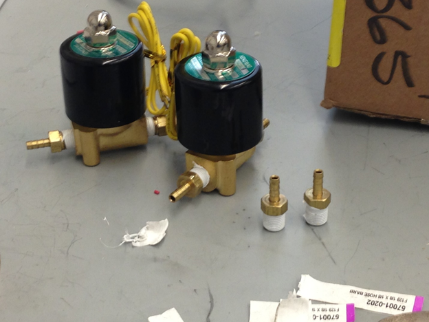
Fluid from each reservoir must pass through a solenoid valve before reaching the pen. These are the second step we take to control fluid flow. While the IV drips control the flow rate, the valves control whether there is any flow at all. When a valve is closed it prevents any fluid from flowing out of the IV drip or from the reservoir to the drip. When the valves are open they allow fluid to flow freely through the system. Each solenoid valve can draw 1.5 Amps and produce a considerable amount of heat, but there is no need to open two valves at a time or for more than a few seconds so these are not real problems for Pinc.
Design Process
We realized early on that valves were going to be a necessary part of our system. We decided to use solenoid valves because their binary on-off nature made the control software simpler to create. When we were sourcing the valves we had already bought 1/8 inch tubing which we found to allow a good amount of ink flow and to interface well with our pen and reservoirs. Therefore, we bought solenoid valves to handle 1/8 inch tubing, the corresponding barbed pipe fittings and Teflon tape. The electrical system was designed around these valves.
Overview
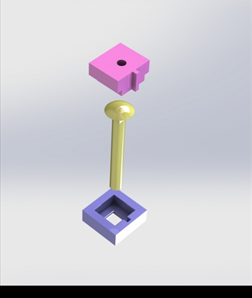
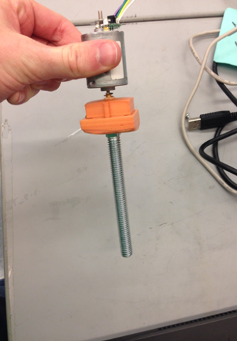
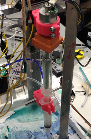
This is the last step in our fluid control system is the ink expulsion chamber. This is syringe that is adapted to take in ink and water from the side and to release them out of the bottom. For inks, this step has no effect on their travel. However, when water is being run through the system, a DC motor turns a screw which moves the syringe plunger up and down, forcing water through the pen.
Design Process
The ink expulsion chamber was one of the most difficult systems to create. Its necessity was twofold: the first reason is because when we want to clean the pen, we have to force water through it to flush the leftover ink out. The second reason is that it can double as a mixing chamber in the future should we continue with the project.
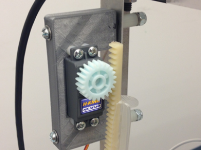
The first difficulty facing this chamber is that it has to be air tight. While it is possible to force fluid to flow out of the pen tip, there is a lot of resistance, and ink would rather flow along almost any other path than through the pen, even if that means flowing up. We found that a syringe was well suited to solve this, but this raised another difficulty about how to move the syringe plunger up and down. Our first attempt was to use a servo powered rack and pinion but this encountered many problems. The first was that the syringe plunger, and our plastic rack gear were not rigid so they would flex away from the pinion rather than be pulled down by it. We introduced a wooden backdrop to prevent this flexing, but then the plunger would rotate and the rack and pinion would become unaligned. We diagnosed this problem as being due to the rack and pinion not being perfectly aligned in the first place and this problem would have been very hard to solve without much more precise manufacturing than we were ready to do. Finally, even if we had solved all of these problems it is unlikely that the servo would have had enough torque to push the plunger down reliably.
Our current solution is to use a screw to raise and lower the plunger. A long bolt is turned by a 12V DC motor which is at a fixed height. The syringe body is also at a fixed height. A nut is fixed to the plunger so as the bolt turns, the plunger is raised and lowered. Because our force is now along the same axis as the plunger’s motion, there is no misalignment of the pieces.