ELECTRICAL DEVELOPMENT
bless arduinos, breadboards, and much much wire debugging.
The circuitry connects the Arduino to the various components we use, specifically the color sensor, the solenoid valves, the motor, and the debugging LED lights. We built the circuits on a small breadboard. While all the components are controlled by the Arduino, we power the motor and the solenoid valve through a separate 12V power supply.
Color Sensor
The color sensing module we used for our project was the TCS-3200, a completely integrated sensor module. Using the TCS-3200, we are able to read any color as a combination of RGB values. To aid reading consistency, we surrounded the color sensor with a box to block out external light noise, and we wrote a calibration program that is able to save the calibrations to the Arduino EEPROM. These features enable us to reuse calibrations between sessions. The TCS-3200 has 8 pins, but the IC we used had an additional input to power white LEDs that improve the reading. Pins S2 and S3 are used to select which color filter is active, red, green, or blue. The sensor outputs a square wave with a frequency proportional to the intensity of light measured. Pins S0 and S1 determine a scaling factor on that frequency. The color sensor runs off the Arduino’s 5V power rail.
Solenoid Valves
Despite much inquiry, we were not able to obtain pen ink cartridge sized solenoid valves for a reasonable price. So we opted for the most realistic option - 12V ¼” inner diameter solenoid valves. One of the first challenges we encountered was powering the solenoid valves. Because the Arduino could at most provide 5 volts, we incorporated a separate 12 V DC power supply to provide the necessary power. We installed the female barrel jack connector on the voltage and ground rails.
After accounting for power, we needed to make sure our connections could handle the required amperage. Seeing how the ammeter measured the solenoid valve’s current consumption at 1.5 amps, we proceeded to research tolerances for the breadboard and the wiring. Figuring out that the 22 gauge wire could not handle more than .92 amps, we wired the solenoid valves with strong 18 gauge wire rated for 2.3 amps. We also found out that most people try to avoid going above .5 amps on the breadboard. Since it was an unofficial rating, and previous research experience resulted in our breadboard continuing to function, we decided to take that opinion with a grain of salt and stick to running only one solenoid valve at a time.
In addition to making sure the components could competently carry current, we also needed to make sure that we could control the solenoid valves while powering them independently from the Arduino. To solve this problem we looked into MOSFETs, and decided to use the PSMN022-30PL N-Channel enhancement mode MOSFET as a means of control. By sending voltage from the Arduino, we control the conductivity of the MOSFET and thus are able to actuate the solenoids as a result. It took some trial, error, and magic smoke, but we managed to figure out how to properly wire and setup the MOSFET for each valve.
Motor
Once we had the infrastructure in place, the wiring for the motor was simple. We used another MOSFET and a diode connected to the 12V rail to protect against the “kickback” voltage when the motor stops. Then we simply attached one pole of the motor to the diode, and the other to ground.
Circuit Diagram
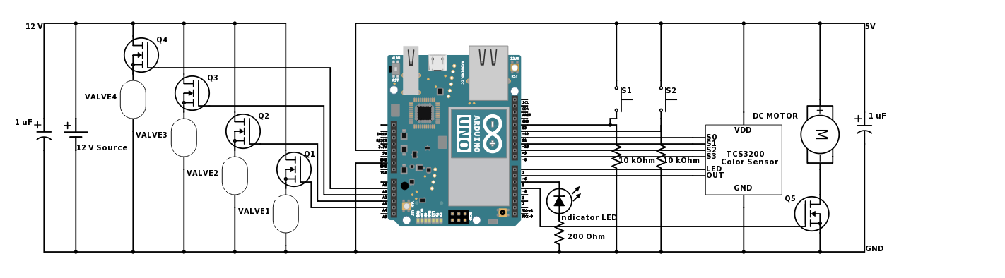
(see, it says Uno. It’s definitely an Uno. Not some Arduino Yun that had “Yun” overwritten with “Uno”)