The Electrical Subteam
We're here to make sure nothing explodes or catches on fire.
In this project project, we are using one Arduino Mega, one trinket (mini Arduino), twelve HXT900 servos, six GP2Y0A02YK0F infrared distance sensors and one LED strip. The schematic of the circuit is shown below:


As the power source’s capacity is 8A, the circuit won’t run short on current. But since all the wires available in the POE lab are 22 gage with a current capacity around 1.5 A, we decided to set up two circuits sharing the same power source. The first circuit will be consisted of the Arduino, servos and IR sensors while the second circuit will contain the Arduino trinket and LED strip. In this way, we are able to use wires of different gages in the two circuits to make sure the currents in both circuit are within safe range.
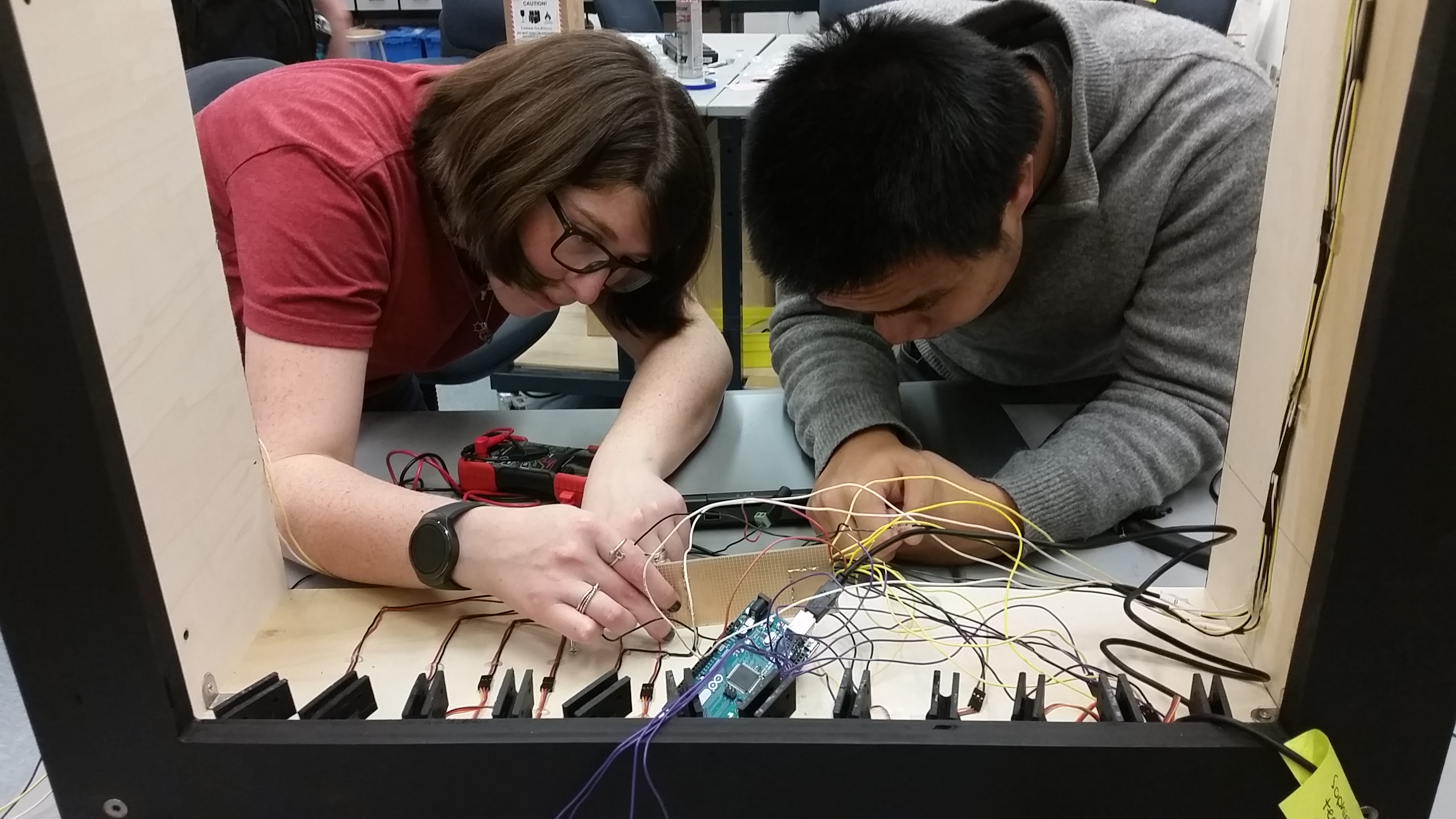
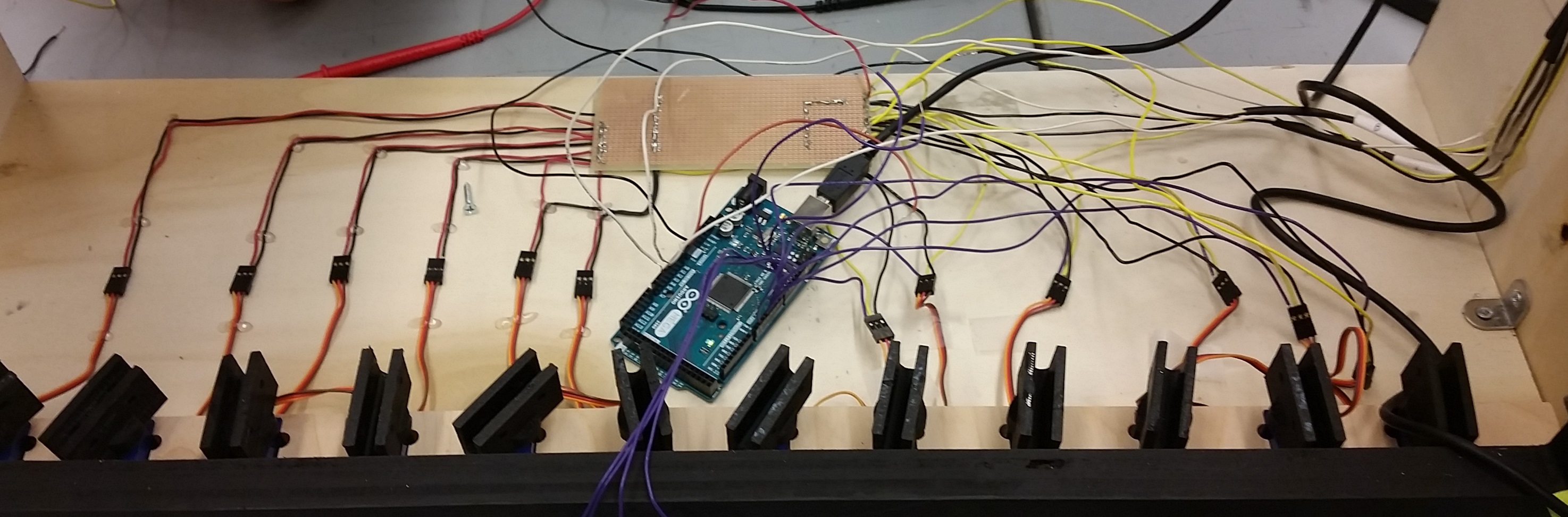
The other major decision we made for the electrical design is setting up the wire management system. During the early stage of the project, the wiring of the system is both messy and unstable (pin comes off very often). So we decided to solder the whole system onto protoboard, sort out the wires and label each of them. A comparison of the system before and after the wire sorting is shown below.