Mechanical Design Goals
When our team settled on making an interactive, sculptural POE project, we realized that the mechanical system would be the ‘face’ of the project. As such, it was important to us to create a system that was robust and functional. It should not break, and its movements should be varied enough that the inputs it receives from the sensors in the electrical and software systems are reflected in an interesting way. The mechanical system had to house all of the electrical components so that they would not be seen, and should be easily assembled and disassembled if components of it ever needed to be replaced. With that in mind, we brainstormed forms that our mechanical system could take before moving forward.
Brainstorming and Inspiration
We quickly realized that an interactive sculpture, while exciting to us, was a nebulous concept, and one of the greatest challenges when working with an idea like it is to concisely define what the structure will look like. We tried to define our system a number of ways before settling on our final design.
First, we tried to scope out what was possible in our three sprint period. We brainstormed different mechanical systems, like geneva mechanisms and unusual linkage assemblies, that could produce interesting movement in response to input from the sensors we chose for the electrical system (at the time, this was a microphone, photodiode, accelerometer, and camera.) Ultimately, we settled on a mechanical system that was not complicated on its own, but when multiplied could produce a number of interesting motions: a four bar linkage.
As our mechanical brainstorming became more concrete, we ended up looking to extant kinetic sculptures for inspiration. Already on our minds were Strandbeests, giant beachwalking sculptures by Dutch artist Theo Jansen, which were on tour in and around Boston at the beginning of the semester. We were taken in by the huge fabric-covered fins on the tops of many of his sculptures, and used these as the basis of our aesthetic design.
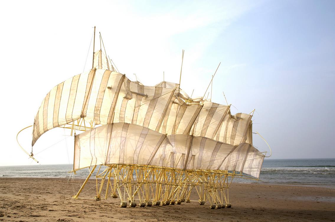
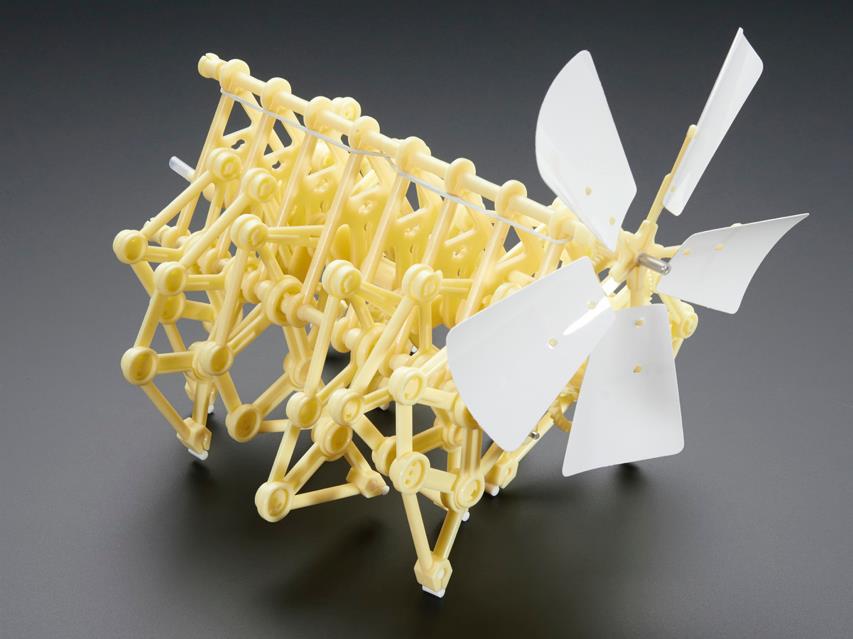
To help get an idea of hose these sculptures worked up-close (and because it was pretty fun) we bought a small model kit of a Strandbeest to play around with.
Iterative Process
With eight weeks to work, we worked to incrementally build a system of four-bar linkages controlled by motors that mimicked the sails of the Strandbeest. We worked with lasercut MDF and 3d printed components to build the majority of our components for all of our sprints, so as time progressed, we had a better understanding of how to use the materials we were provided with.
Designing 4-Bar Linkage
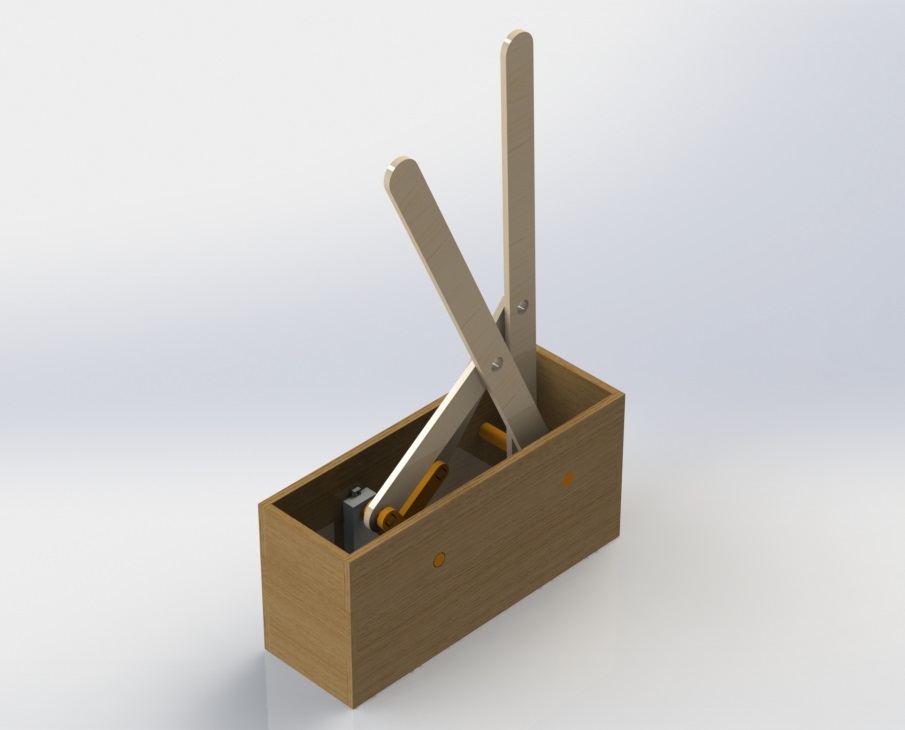
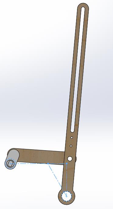
We decided to use crank-rocker 4 bar linkages to approximate the fan-like motion of the Strandbeest’s fins. A 4 bar linkage, while the simplest closed-chain linkage that can be made, presented a challenge to design. In order to produce a proof-of-concept, our first sprint assembly had a basic crank-rocker assembly that was designed in Solidworks, with little thought of its angles of motion.
Here’s a video of our first system in motion:
When it came to designing the linkage our final product would use, we used a geometric design method outlined by a powerpoint created by Ariel University. We created a linkage that had a 20 degree range of motion and had an time ratio of 1. We kept the range of motion of the spines fairly low to account for the fabric that would be woven through them- if it were too high, it would be difficult to keep the fabric taut for the sculpture’s entire range of motion.
From Crankshaft to Individual Actuation
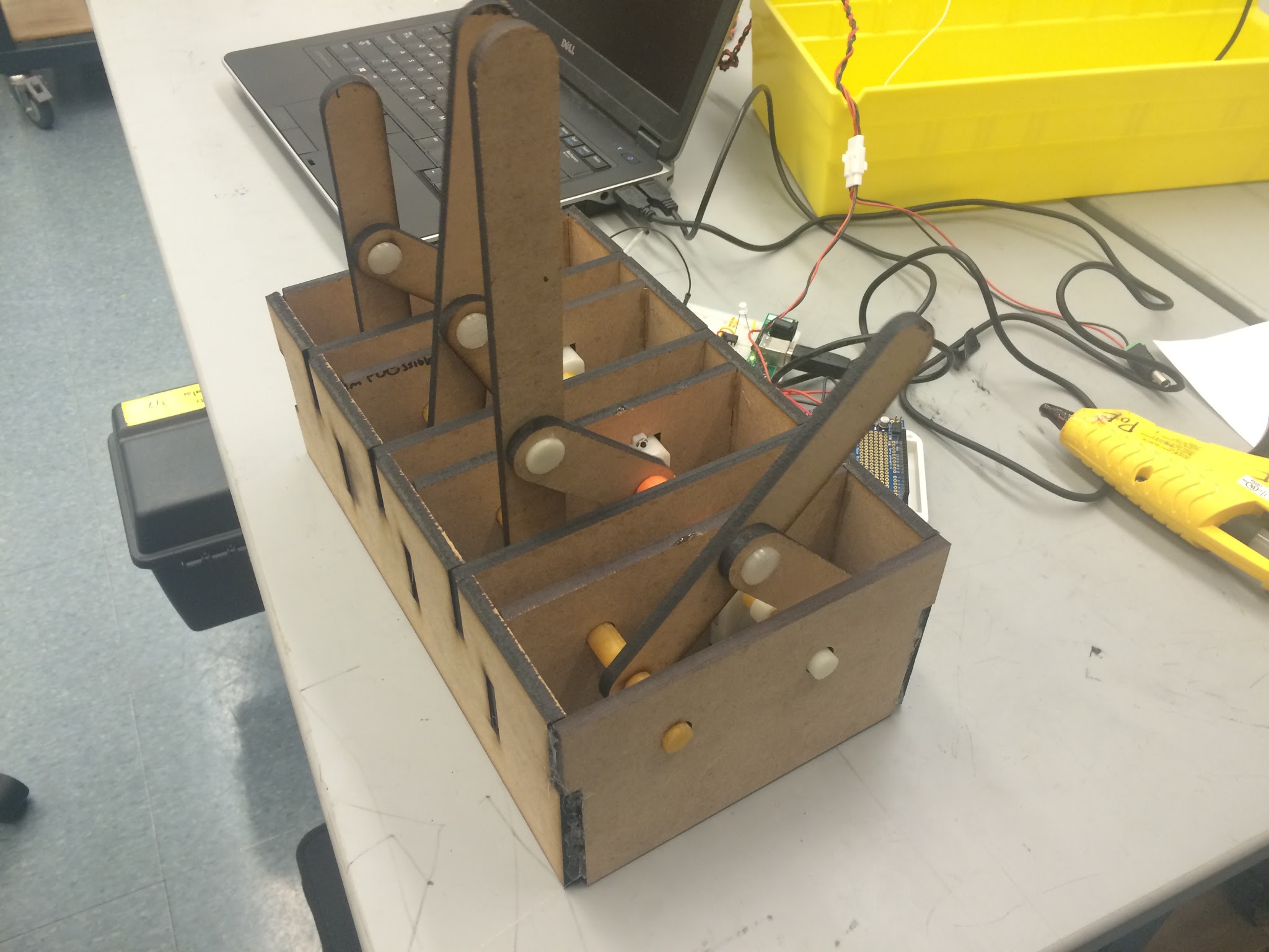
Our first assembly had a single motor driving a series of 4 bar linkages. To do this, we 3d printed a series of interlocking pieces that formed a crankshaft and drove multiple linkages without interfering with their motion.
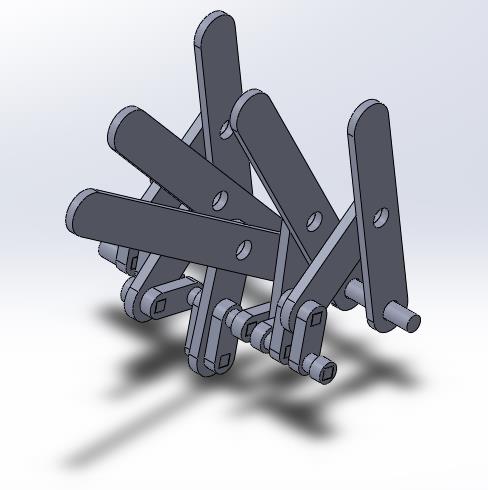
When we moved to individual actuation in sprints 2 and 3, we switched from a long, unstable crankshaft to a series of short cranks each powered by their own motor. This gave us control of individual spines in our assembly.
Slots for Assembly
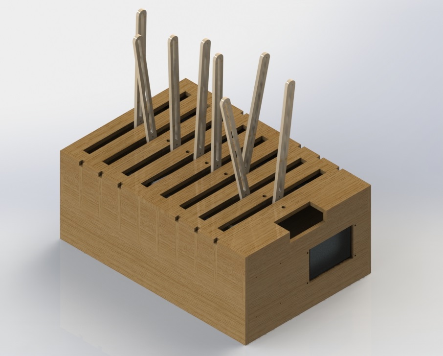
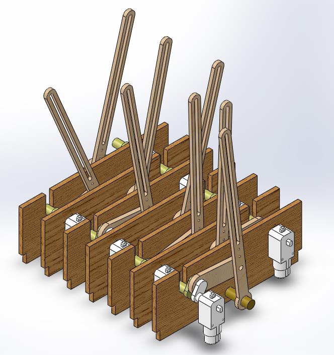
When we built our first assembly, we were more worried about creating a working assembly than what would happen to it after the fact. We learned later on that having an assembly with many moving parts (like eight individually actuated 4-bar linkages) needed to be disassemblable in order to fix pieces in case they were damaged or fell out of place. In our final assembly, we accomplished this in a number of ways. First, the side plates of our sculpture’s base have slots for the plates that hold our motors. These can be slid in and out of the assembly without having to take apart the entire sculpture.
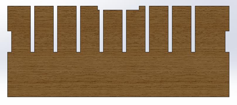
The 3d printed crank components of our sculpture also slide into slots, this time on our motor mount plate, that allow the pieces to be removed without disassembling most of the sculpture.
Our old assemblies required removing several pieces of MDF to get to individual motors during a malfunction. We believe that the new design makes it easier to operate and modify our final sculpture.
Common Problems
While building our mechanical systems, a number of problems arose that we did not expect. Overcoming them was a challenge, but ultimately a rewarding experience that contributed to our learning.
Tolerancing, Lasercut and 3d Printed
Lasercutting was new to our POE team at the beginning of the semester, but we had to become accustomed to it quickly if we were going to make a kinetic sculpture out of MDF. We quickly learned that for us, often the kerf in the lasercutter produced pieces that were slightly off from our measurements in CAD, but did not severely affect performance of our linkages. The majority of our difficulty was surrounding 3d print tolerances. In our experience, the differences in performance between printers ended up producing parts that had different tolerances, so no matter what tolerances we built into our CAD, we would need to modify our parts once they had printed to ensure a fit. While we were able to solve the problem, we could have avoided it by getting our own personal filament and not using the communally-available rolls and saved time in assembly.
Stepper Motors vs. Vigor Motors
The first two iterations of our sculpture used vigor motors we found in the mechanical engineering stockroom. We had planned on switching to stepper motors after proving to ourselves that we could have a functional, moving assembly that was toleranced properly and changed behavior based on inputs from a webcam. In sprint 2, we bought eight 28BYJ-48 motors from You-Do-It Electronics and Needham and Adafruit. We had difficulties with them from the start. We could not find adequate documentation on the steppers’ current draw, and had difficulty using the Arduino stepper library.
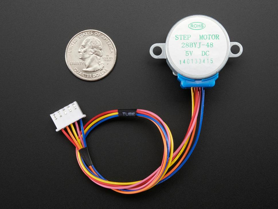
Unfortunately for our team, the troubles with the steppers did not end there. We found that the four motors we bought from You-Do-It and the four motors that we bought from Adafruit had completely different behaviors when subject to the same load. Additionally, the torque provided by the stepper was so low that the motors couldn’t spin our lightweight 4-bar linkages. After a lot of suffering and deliberation, we realized that we needed to cut our losses and switch back to the motors we started the project with, which were freely available, provided enough torque to move our mechanical system, and easier to control. The lack of stepper control in our project meant that we had less control how our sculpture’s spines moved, and patterns it created could not be as complex as we hoped, but we felt it was more important to create a functional product in time than wrestle with the impossible.
Turnaround Time
As expected when starting the project, the difference in turnaround time between the mechanical, software and electrical systems was apparent from the start. Whereas errors in the software and electrical systems could be fixed at any time, fixing mechanical system errors often meant having to wait for the machine shop to be open, printers to be available, or materials to arrive at Olin before any changes could be made. These factors often pushed back integration time to the last few days of each sprint.