The electrical components of this project acts like the glue between the other components, standing between the overlap of mechanical and software design. The electrical component of the project consists of the accelerometer, photodiode, and LEDs.
Accelerometer: Knock-Knock!
The accelerometer is used to toggle a pattern with the output LEDs. The accelerometer is placed inside of the box, attached to the wall. The user knocks on a selected area of the wall two to three times to toggle LED patterns. This process is achieved using electrical filters and amplifiers, and processing using Arduino.

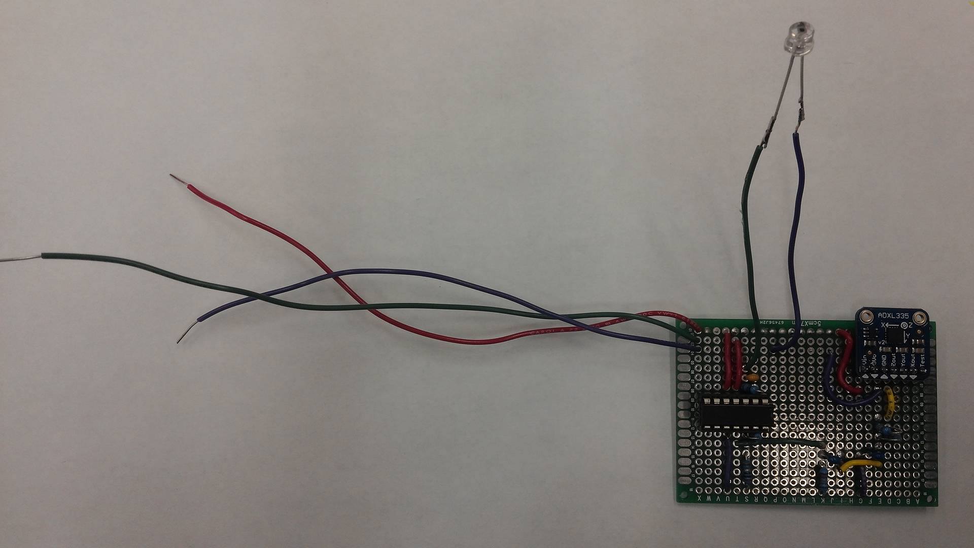
The chip can sense acceleration in three directions, and is powered by the Vs port with a power source of 5 V. The COM port is ground, which was connected to the ground of an Arduino Uno. Only the Zout output was used when sensing acceleration caused by knocking, as by design, the knocking would cause the chip to move up and down in the Z direction.
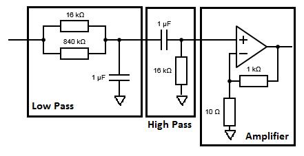
The Low Pass filter is used to filter out a lot of the noise present in the signal. The cutoff frequency, determined by the values of the resistor(s) and capacitor, is approximately 100 Hz. It is important to note that the resistors are used in parallel. The cutoff frequency is found by the following equation (f = 1/(RC2pi)). Similarly, the High Pass filter is used to filter out the acceleration of gravity from the signal. The cutoff frequency is at 9.9 Hz, found by using the cutoff frequency equation above.
The amplifier is a non-inverting amplifier, which uses the LMC6484in operational amplifier chip. The amplification can be found with the following equation where (A = (R1/R2)+1), where R1 is 1Kohm in this case, and R2 is 10 Ohm. The total amplification is 101 times.
The Arduino will track if the signal surpasses a certain threshold, and will count until three to identify three sharp increases in the signal as a knock. After each time the signal passes the threshold, the Arduino will not recognize signals that pass the threshold for a certain period of time (300 milliseconds) to stabilize the signal, as each knock may have aftershocks and multiple instances of signals passing the threshold. Once three knocks is recognized, the desktop companion will toggle a LED pattern.
Photodiodes: Bright Lights!
The photodiode will measure the brightness of the room, and overall influence how bright the LEDs will glow. The photodiode we are using is the Osram Opto SFH 203. We opted to use a photodiode ahead of a photoresistor because, although the photoresistor is easier to use, it is difficult to calculate the accurate change in resistance in photoresistors due to their low quality.
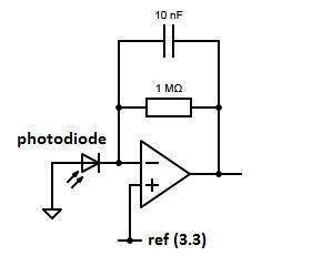
The photodiode converts light energy into current, so no power source is needed, other than what is used to drive the Op Amp, which is yet again the LMC6484in. The Op Amp draws no current, so all the current goes through the resistor. The voltage output is therefore determined by Ohm’s Law, where (Vout = I * R), where current is directly related to light intensity sensed by the photodiode, the resistor is the 1 Mohm resistor in this case, and the Vout is the output voltage, also influenced by the reference voltage. The reference voltage adds the voltage value to the final output. The capacitor is placed to create a low-pass filter, where the cutoff frequency is (f = 1/(RC2pi)), and in this case is 16 Hz. This would prevent the alternating AC lights from creating a signal that is unnecessary.
Individually Addressable LEDs: Rainbows!
The LEDs add character to the mechanical aspect of the sculpture by adding color. In order to maximize the color combinations and patterns that the LEDs would be able to display, we decided to build individually addressable LEDs, or LEDs that can be individually selected to display a certain color.
To prevent the LEDs from burning out, we needed to add current limiting resistors. We knew that we would be providing 5V to the LEDs, and with a forward current of 20 milliamps, we were able to calculate the necessary resistor values. We ended up using 158 ohm resistors for the red LEDs (155 ohms was ideal) and 86.6 ohm resistors for the green and blue LEDs (85 ohms was ideal).
Because there were not enough digital PWM pins on the Arduino Uno to control all 8 of our tricolor LEDs, we used shift registers to "add" more PWM pins to the Arduino. Shift registers work by reading two signals: a clock and a signal. Each "bit" of the signal tells the shift register to turn a pin on or off, but the clock is what tells the shift register at what rate the signal should be read. Utilizing three shift registers and the ShiftPWM Arduino library, we were able to implement individually addressable LEDs.
Process: From Planning to Protoboard
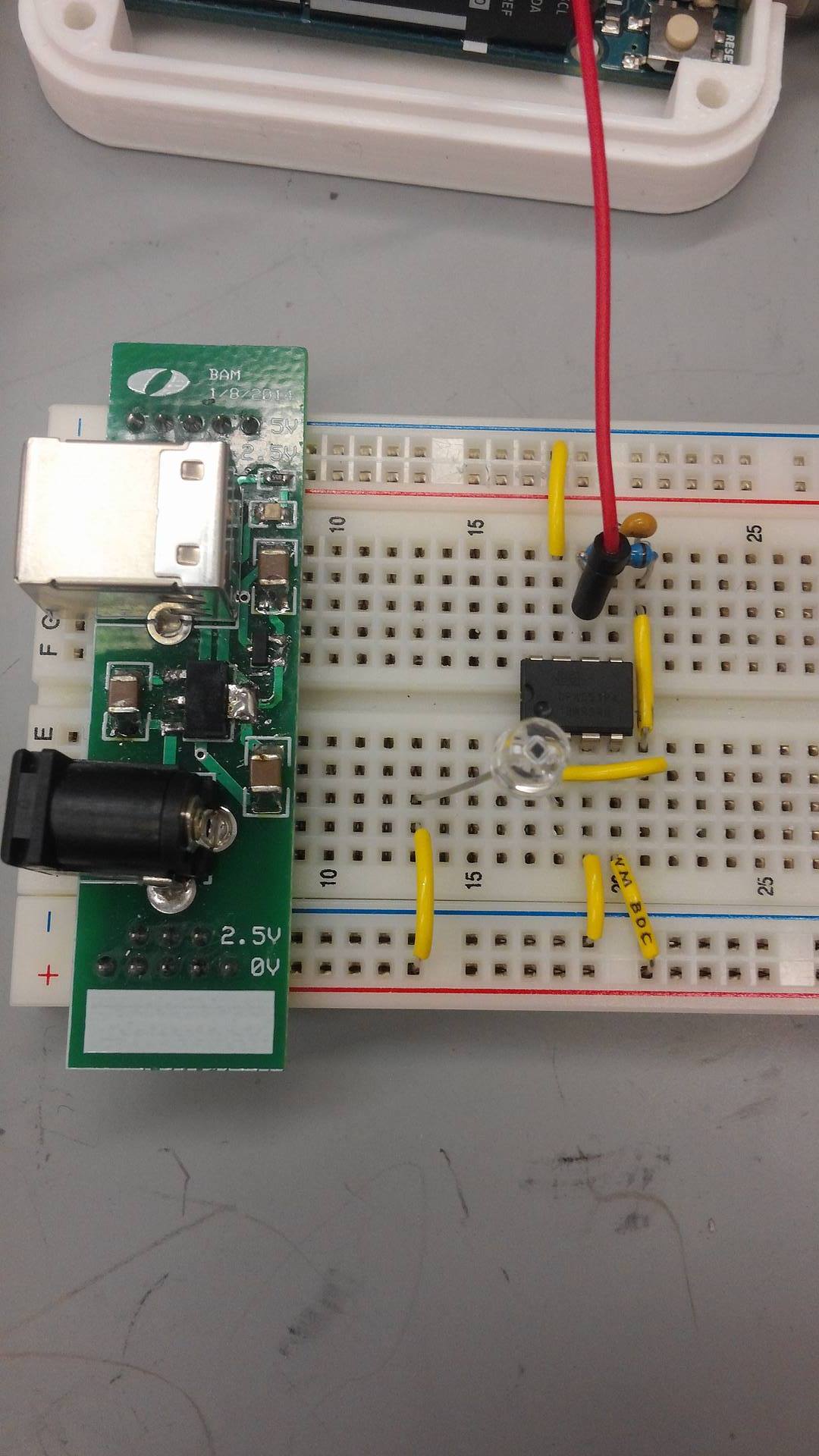
Initially, the components were tested. For example, the photodiode circuit was built by using a previous example circuit from the class (Introduction to Sensors, Instrumentation, and Measurement), and had the output signal connected to the input of an Arduino input, and read the values.
A similar process was implemented for the accelerometer, as the initial circuit was breadboarded and tested with the Arduino. The Analog Discovery also was used to track the sharp changes in voltage with each impulse on the accelerometer chip. The Analog Discovery showed the voltage range the output of the accelerometer took place in, and helped filter and amplify it.
After both circuits were thoroughly planned out, the two circuits were put on the same protoboard. The protoboard was compact and allowed the circuitry to be placed in the final sculpture taking up minimal space.