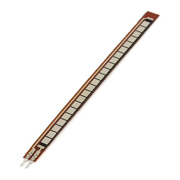
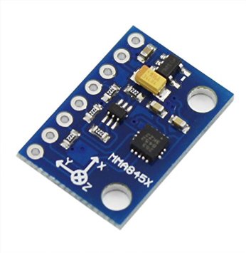
The electrical components of the system consist of five flex sensors, an Arduino, an accelerometer, a bluetooth connector, and an Android phone. These components were necessary in sensing the position of the user’s hand and fingers (based on accelerometer data and resistance values) and translating the data into letters (that would eventually turn into text). To control these components we used an Arduino integrated with the following circuits on a protoboard so that we did not need a large breadboard on top of the hand. All of the datasheets on each of the elements below can be found on the how-to page.
The accelerometer and Bluetooth boards need to be powered by 3.3Vs instead of the 5V produced by the Arduino. To do this, we use a voltage divider with resistor values of 50K and 30K Ohms for the accelerometer, producing a voltage of 3.125V and a voltage divider with resistor values of 20K and 10K Ohms for the Bluetooth board, producing a voltage of 3.3V. The accelerometer output for x, y, and z is read by analog pins on the Arduino, and the Bluetooth output is read by a digital pin on the Arduino. The Arduino communicated with an Android device via Bluetooth using S2 Terminal for Bluetooth

One major problem we sought to address was the amount of bulk created from all of the electrical components. To minimize the problem we used an arduino pro mini, which has the necessary number of analog inputs (8) for both the flex sensors and the accelerometer. We used a USB adapter to upload code onto the board.

Flex sensors are essentially very long resistors that change resistence depending on how much they are bent. We used 5 4.5in sensors in order to detect the bend of each finger, and they were each sewn into a pocket on the inside of the glove. They were integrated into the software through the Arduino's analog read function. In order to prevent burnout, we calculated that each flex sensor required a pull-down reistor of ~20,000 ohms. The schematic for a basic circuit can be see below.

Because many of the letters in the ASL alphabet are similar, we used an accelerometer to increase the accuracy of the glove. The accelerometer measures the acceleration along the x, y, and z axes which can be used to differentiate letters that have the same shape but are in different oritentations. The accelerometer needs to be powered at 3.3 Volts but the flex sesnors require 5V, so we used a voltage divider in order to prevent burnout of the accelerometer. The schematic of the circuit can be seen below.

In early iterations, we used an LCD screen to print the letters corresponding to the ASL sign so that users did not need to use a computer to communicate. However, this method still required the use of a breadboard, which was very bulky, and we believed that we needed a more simple and less clunky method. The schematic for the LCD we used is below, and we obtained much of this information from the Arduino resource page.

In order to improve the user's experience with the glove, we implemented a Bluetooth recevier into the design. The bluetooth connects to an Android app and prints the letters being signed onto the screen. This eliminated the need for the LCD display from earlier iterations.

We used two 2032 3V coin cell batteries from Energizer in series to power our Arduino and other electrical components. This allows for the user to be free to move about rather than wired to a computer or wall for power. The Arduino accepts the raw input of ~6V and brings it down to 5V for the five flex sensors. Because the Bluetooth receiver and the accelerometer both run off of ~3V rather than 5V, we designed two voltage dividers to drop the voltage before powering each of them. These can be seen in the schamtic below.
© Hextal. All rights reserved. | Design by TEMPLATED and Annabel Consilvio.