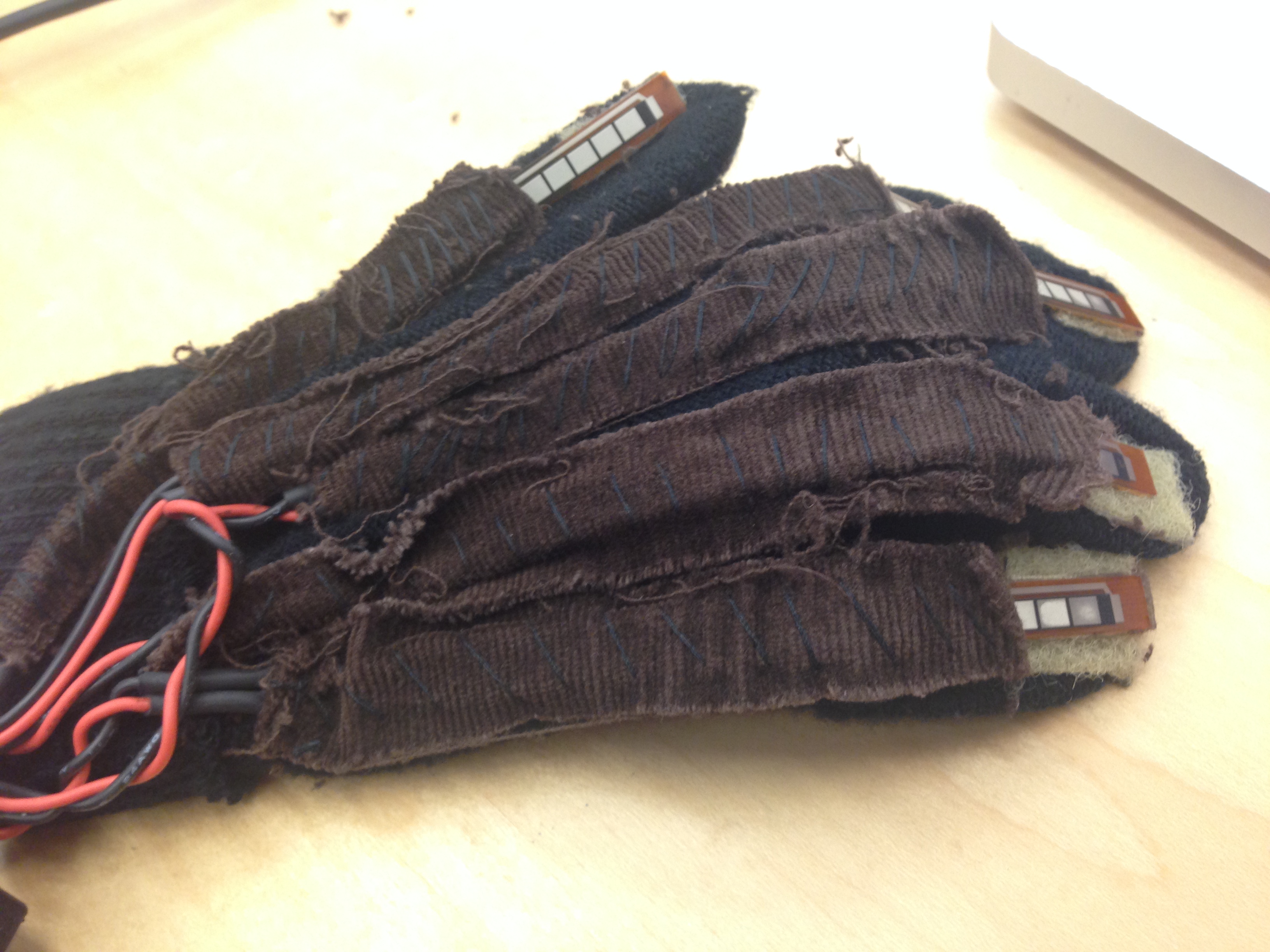
Here’s a list of everything you’ll need in order to make your own ASL interpreting glove:
The following table shows everything that was purchased during this project. Asterisks indicate that we obtained this item for free and the cost is therefore estimated. The table below the Final Product Total includes items that we purchased during development including items used in the final product.
| Item | Cost |
|---|---|
| 2 3V Coin Cell Batteries CR2032 | 4.00 |
| 5 4.5" Spectra Symbol Flex sensors | 64.75 |
| Arduino Pro Mini | 13.95 |
| Arduino Converter | 24.06 |
| Connector Cable | 4.53 |
| Bluetooth Receivers | 6.37 |
| SparkFun Triple Axis Accelerometer Breakout: ADXL337 | 9.95 |
| 2 Sparkfun Snappable Protoboards | 7.95 |
| Glove* | .00 |
| Thread* | 1.00 |
| Fabric* | 5.00 |
| Wire* | 3.00 |
| Velcro* | 2.00 |
| Final Product Cost | 149.56 |
| Item | Cost |
|---|---|
| 6 3V Coin Cell Batteries CR2032 | 16.00 |
| 5 4.5" Spectra Symbol Flex sensors | 64.75 |
| 1 2.2" Spectra Symbol Flex sensor | 9.63 |
| Arduino Pro Mini | 13.95 |
| Arduino Converter | 24.06 |
| Connector Cable | 4.53 |
| 1 Bluetooth Receivers | 12.74 |
| Triple Axis Accelerometer: GY-45 | 7.99 |
| SparkFun Triple Axis Accelerometer Breakout: ADXL337 | 9.95 |
| Triple Axis Accelerometer: SEN09836 | 18.95 |
| LCD Screen* | 7.00 |
| 2 Sparkfun Snappable Protoboards | 15.90 |
| 5 Square 1" Single Sided Protoboard | 7.50 |
| Glove* | 3.00 |
| Fabric* | 5.00 |
| Thread* | 1.00 |
| Wire* | 3.00 |
| Velcro* | 2.00 |
| Total | 225.95 |
You will need access to a 3D-printer to make the band that houses the electrical components. If you don’t have access to one, any material comfortable to wear with a housing attached should work. Here are the CAD, STL, and X3G files we made. The CAD files require SolidWorks to view and the X3G files require MakerBot Desktop, but the STL can be viewed with several different software programs. Download CAD files.
We chose to use the Arduino Pro Mini because it has 8 analog pins, which is how many we need (5 for the flex sensors and 3 for the accelerometer). Different accelerometers might require different pins.
We found it more comfortable to stitch pockets for the flex sensors on the inside of the glove, on the palm-side of your hand so that the sensors are inside of a closed fist. This restricts less motion than having the sensors on the outside, and looks better as well. We used small pieces of velcro to hold the tops of the flex sensors at the top of the fingers inside the gloves.

The Bluetooth receiver module is only compatible with android phones and devices. We used S2 Terminal for Bluetooth, an app available for free on the Google Play Store. Our early iteration used LCD instead of Bluetooth. We found Bluetooth to be easier to use, but LCD should work as well.
The perf board should ideally be as small as possible. Additionally, you should have a variety of threaded wire, solder, a soldering iron, and flux on hand to attach everything. If you don’t have any soldering experience, there are several tutorials online that are helpful.
© Hextal. All rights reserved. | Design by TEMPLATED and Annabel Consilvio.