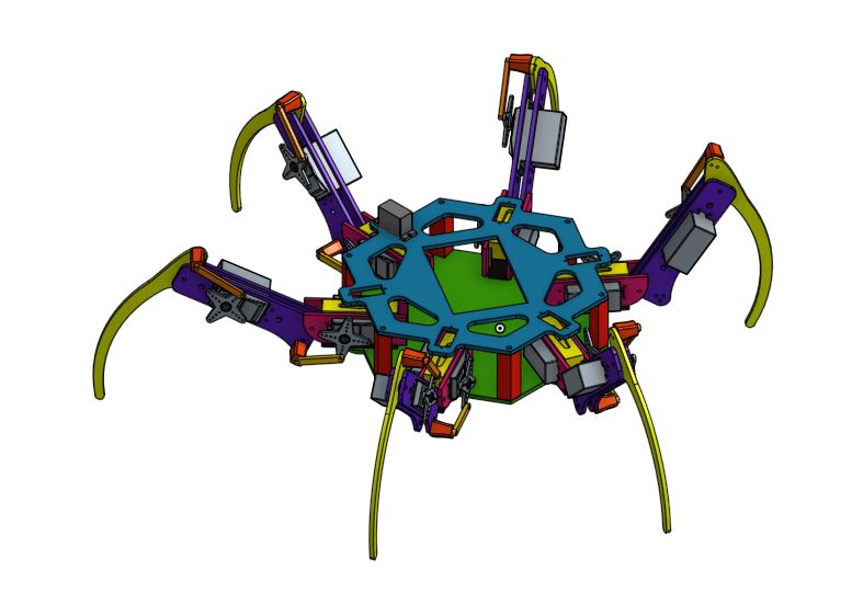
 Full HExBOT Assembly Full HExBOT Assembly
|
This IS THE MECHANICAL DESIGN FOR THE WHOLE HExBOT. IT CONSISTS OF 6 LEGS, 6 SPACERS, AND 2 BASEPLATES. |
|
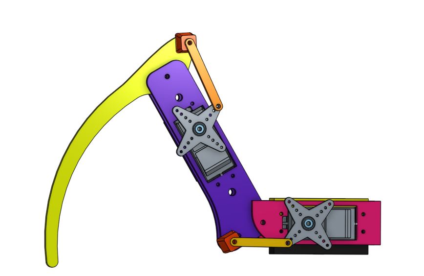
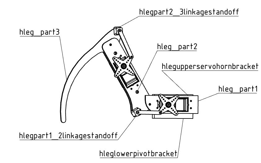
This is what each leg looks like(without screws/bolts). The orange pieces attached to the servo horns are actually pushrods on our robot. The purple, pink, and yellow pieces are made out of bass wood. The red pieces are 3D printed out of PLA or nylon.
The pushrods and spacers make sure the leg actuate when the phi and psi servo horns turn. There are 3 legs that look like this and three that are mirrored. Keep in mind that there are two purple and pink piece on each leg--one on each side of the servo. You can see this more clearly in the picture below. |
Full Leg Assembly
|
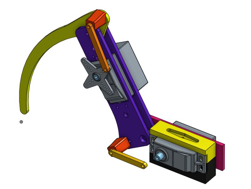
Leg Assembly to see Upper Servo Horn Bracket
Base of Lower Pivot Bracket
|
Here you can see the hidden pieces of our robot. You can see the Upper Horn Servo Bracket and the Lower Pivot Bracket. The Upper Horn Servo Bracket ensures that the leg turns in the theta direction when the servo does. The Lower Pivot Bracket is press fitted on a bearing and can rotate.
This distance is maintained by the spacers in the two body plates which can be seen in red in the assembly image at the top of the page. |
CAD Download Titles
These are all the 3D printed files!
|
|
| ||||||||||
Keep in mind these are SolidWorks files exported from Onshape so some sketches in parts aren't fully defined. Unfortunately we couldn't export a SolidWorks Assembly at this time because Onshape breaks the mates.
|
|
| ||||||||||