|
Today, we found out why the hexbot's legs oscillate when it's sitting still. Servos convert the PWM input into a desired angle. One advantage of digital servos over analog ones is that they always correct toward the desired angle with full power, rather than proportional. They aren't weaker when correcting for small angles. So when our hexbot is sitting still, bumping a leg even slightly from its position will induce a full-power burst of correction until the servo is again at the correct position. Since we have relatively heavy legs on low-friction bearings, the leg's momentum carries it past the zero point, and the servo corrects full-power in the opposite direction, inducing oscillation.  As we've said before, in order to make programming complicated behaviors easier, we're moving all but the PWM control code to a Raspberry Pi. This has the added benefit of saving us the trouble of generating lookup tables for every behavior in MATLAB.
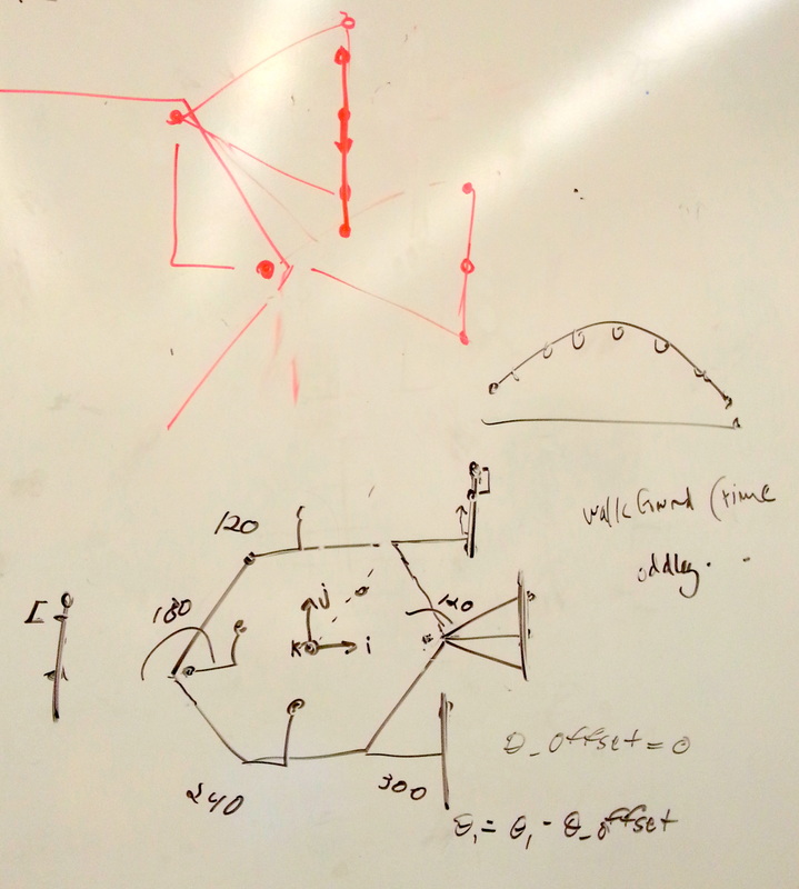
Rocco gave us a crash course in making devices communicate using ROS topics. The Raspberry Pi will be generating an array of 18 servo angles every timestep and publishing it to a ROS topic. The Arduino will be checking that topic for the latest numbers and converting them to PWM output for the servos. To generate the angles, the Raspberry Pi will be referencing a simpler lookup table. It consists of a list of the x, y, and z positions of the foot relative to the body servo of one of the legs at every timestep. That step can then be shifted in space to represent the position of each foot, and indexed to find the desired position at any given timestep. From there, the Pi uses the reverse-kinematic trigonometric equations we derived to determine the angles of each servo. Since we have more experience with Python coding, we are able to use classes and functions across multiple files, and take advantage of ROS's real-time capabilities.
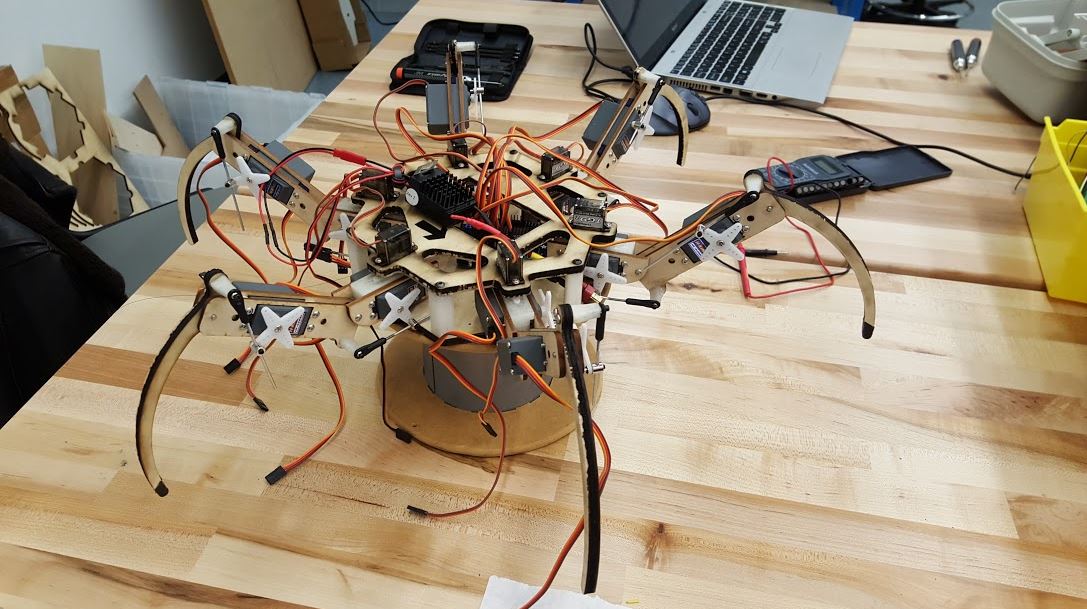
We built a six legged robot that is able to maneuver on it's own power source. We are working on making it follow people around (via a beacon).
Today was another day we let the hex walk on its own. With the changes to the underside of the second leg linkage, the bot has a new failure point. It breaks around the bearing in the second linkage and the crack extends though the rest of the linkage. You can see what this looks like below. 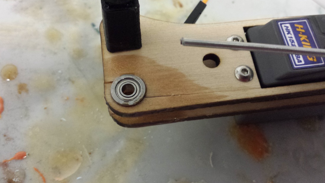 While this was most often the failure point, we also saw a different failure point. The third leg linkage, the curved one, broke while the HExBOT was walking. We think this is because that leg was curved and dragged around the carpet. We believe that this is because the hexbody sags when walking-which makes it think that the position for air is on the ground. To fix these problems we plan to: 1) Coat the legs in epoxy 2) Curve the third linkage such that there is more material around the hole 3) Create an offset to account for the sag. We also plan to move the legs an 1/8 " up so that the push rods "hub" doesn't hit the base plate. Off to make more changes. See our robot try to conquer the world only to get crushed below.
The code calibration has proven to be more complicated and more mind breaking. Between the servos, the Arduino, and the look up tables there are several conversions, offsets and different ranges of angles and values. We spent about an hour just trying to visually figure out what values determine what angles where for which ranges of motion.At this point I think we have a pretty good understanding of what the ranges and angles and conversions are but now and then it still happens that we think that we're going to make the servo move 20 degrees and it instead goes further, far enough to break the joint.
Today, our hexbot stood for the first time. We also broke our sixth femur linkage. And then re-broke some of the others. As you can see in the image below, most of the force on the leg is transmitted through the coxa-femur joint (is there a trochanter in there somewhere? We're a bit fuzzy on our insect analogy.) It's connected to a very thin extension of wood that splits very easily along the grain. We've glued them all at least once now. For the final project, we'll be redesigning 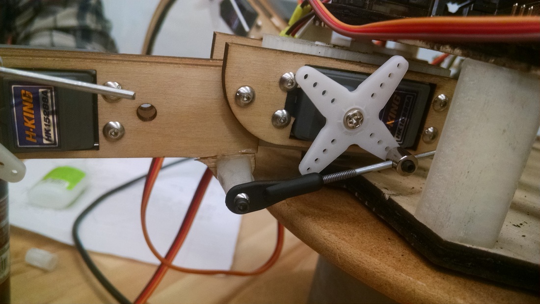 Once we got all the parts cut out...the fun started! It was assembly time for the HExBOT team. Watch a short time lapse of us assembling part of our bot below.
We've also been figuring out how to communicate with the servos through the servo shield rather than directly from the Arduino. While Arduino control uses the convenient Servo.write() function, the servo shield requires the program to specify the range of angles as well as the PWM pulse width. Calibrating the servos has been a bit of a challenge, because the servo horn has to be attached at an agnel that gives sufficient range of motion in the correct direction. Then, in code, we need to determine and correct the offset from the zero point.
|