Mechanical Design
Pan
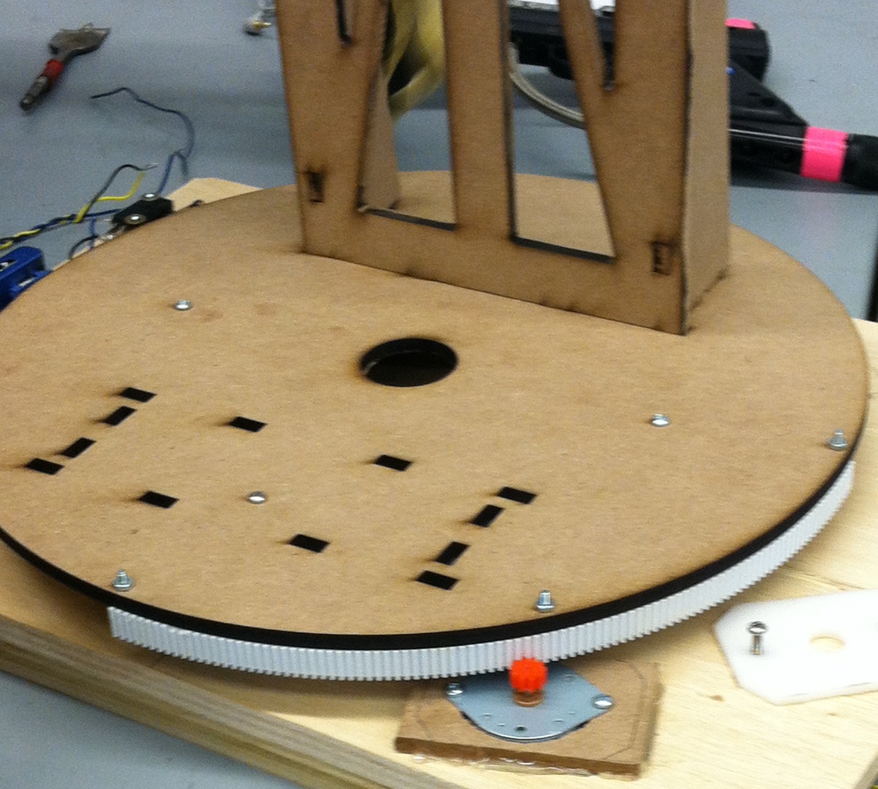
A lazy susan supports the pan surface allowing the marker mount to rotate horizontally.The motion is controlled using a mounted stepper motor that interfaces with a curved gearing rack that we designed and 3D printed. This system has a gear ratio of 1:36 allowing the rack to move at 7.5 degrees per motor step. Limit switches and mechanical stops constrict the marker movement to a ninety degree range.
Tilt
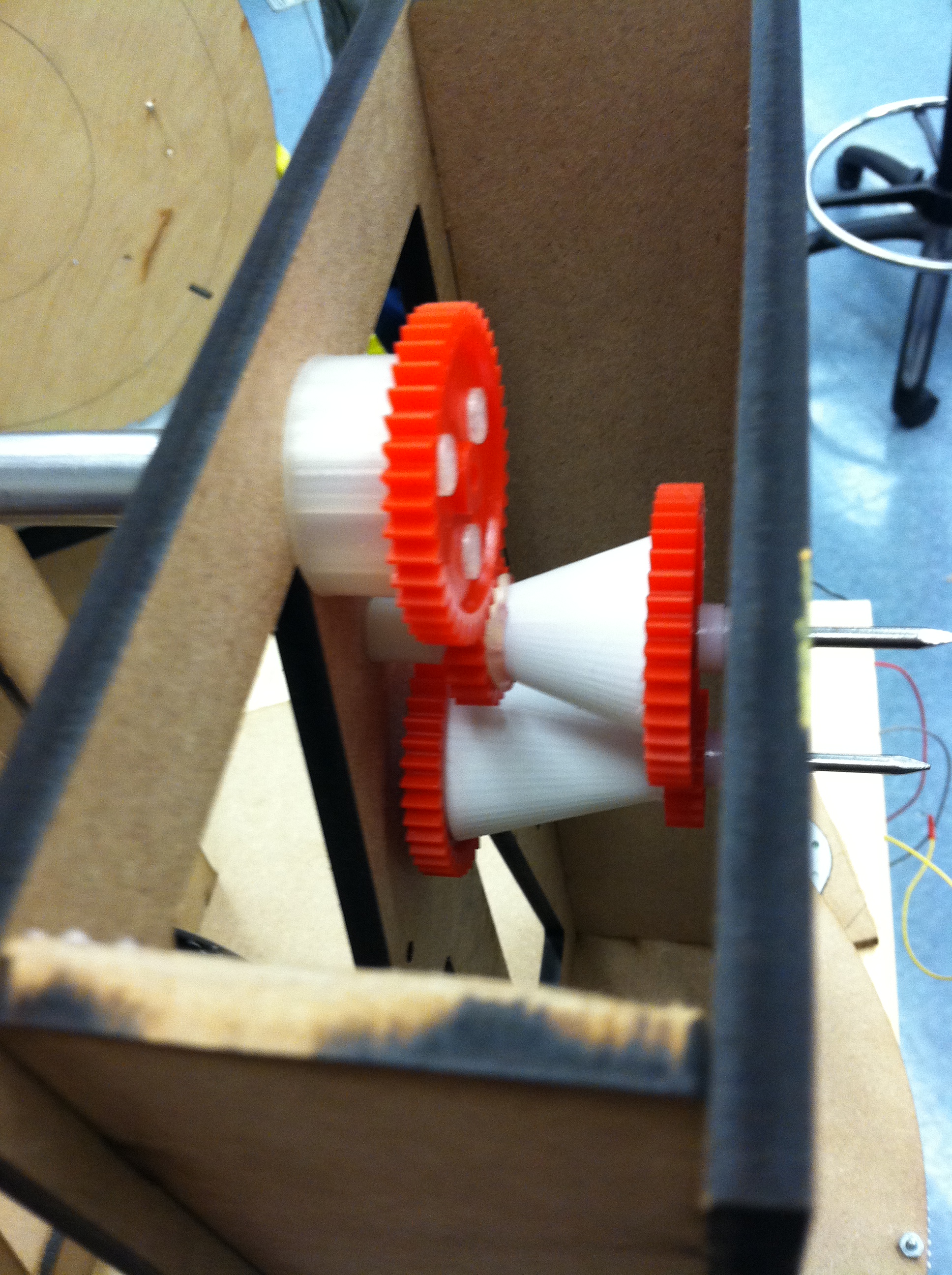
Our system tilts the paintball marker by using a stepper motor to drive a 16:1 custom gearbox mounted atop a laser-cut tower. Due to the tight tolerances required by (and frictional forces inherent in) a multi-stage gearbox, the tilt mechanism proved to be much more of a challenge to design and fabricate than the pan mechanism. Between gear slop, axle friction, and off-center marker weight, our first “production” revision could not reliably tilt the marker. However, after a day’s worth of relatively simple modifications to the marker mounting uprights, we (hopefully) managed to get the marker tilting at windmills like Don Quixote.
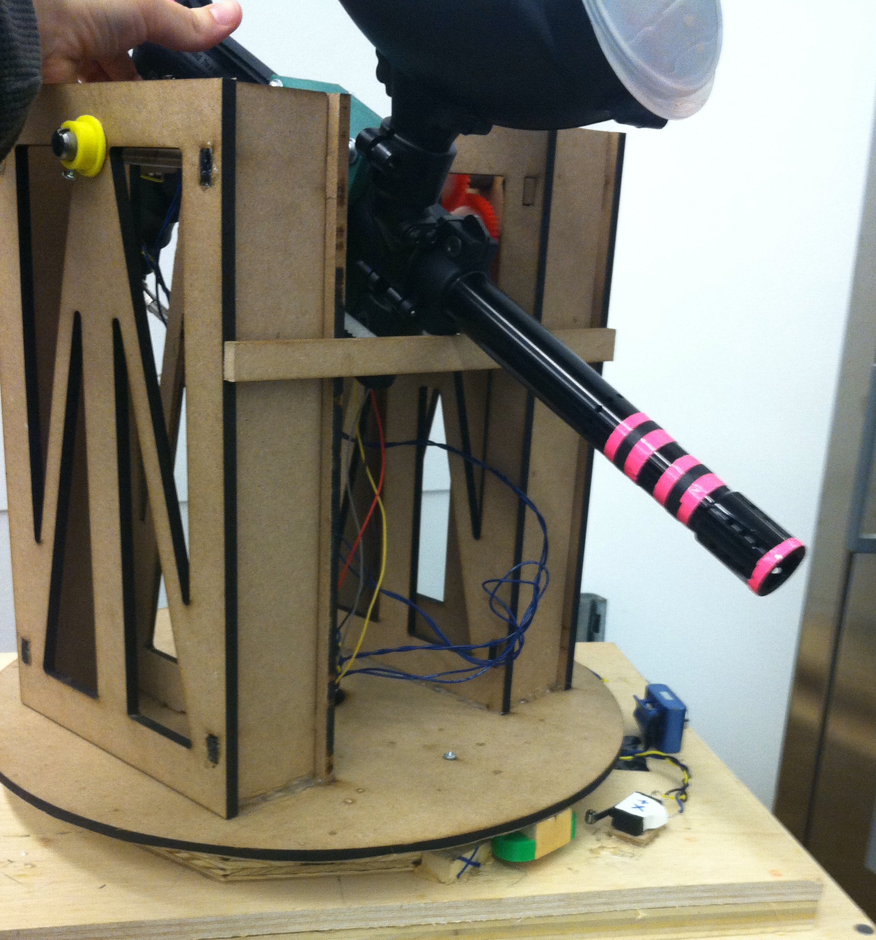
Marker Mount
To facilitate accurate and stable aiming, we custom-CADed and 3D printed a plastic mount that fits around our paintball marker. This mount is the functional heart of our mechanical design: many of the other subsystems, such as the trigger and the tilt gearbox, rely on it. The plastic mount is supported on each side by an axle extending through a pair of 12” MDF vertical uprights. The uprights were carefully laser-cut and assembled for maximum ease of assembly while retaining stability. Speed holes in the side panels allow for easy access to system components during assembly and add style points.


Marker Modification
Before our paintball marker could be safely and easily operated by an autonomous system, we had to make a pair of key modifications. First, we dropped the firing pressure on the marker all the way to its absolute minimum, hoping that this would alleviate some safety concerns by reducing paintball muzzle velocity. Second, we replaced the marker’s internal trigger spring with a weaker spring from a clicky pen so as to enable easier trigger firing. Without the former modification we would not have been allowed to proceed with the project; without the later we would’ve had to shell out for expensive motors to operate the trigger safely.
Trigger
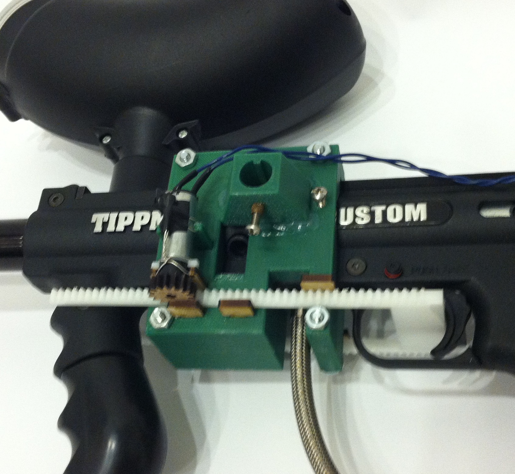
The most surprising mechanical problem of the entire project was the trigger mechanism. After tossing around a few basic ideas at the beginning of sprint 2, we settled on a rack and pinion trigger mechanism powered by two small motors attached to the marker mount. For safety reasons, we initially wanted to have the trigger mechanism pull itself off of the trigger when unpowered - which meant a backdrivable motor. Unfortunately, every motor on campus that was powerful enough to pull the trigger proved to be impossible to backdrive. Our experiments with elastic assists made the trigger operable by weaker motors but effectively prevented reloading. Ultimately, we made the aforementioned “clicky mod” so as to make the trigger pullable by weaker motors, then wired the motors to be reversible by our circuit anyways, giving us best-of-all-worlds performance: powerful, durable, and safe.
Mechanical Safety
Mechanically we have another layer of safety to complement the software and electrical systems. In pan, should the software send the marker to a position too extreme, and the marker travels past the electrical limit switch, the pan gear will first disengage with the rack, making it physically impossible to continue to be driven. Should the marker be carried further by its own momentum, it will next impact upon our mechanical stops, ensuring that it is physically impossible for our marker to ever face towards people behind the podium. In the tilt axis, we have a similar set of mechanical stops should motion continue past the limit switches.
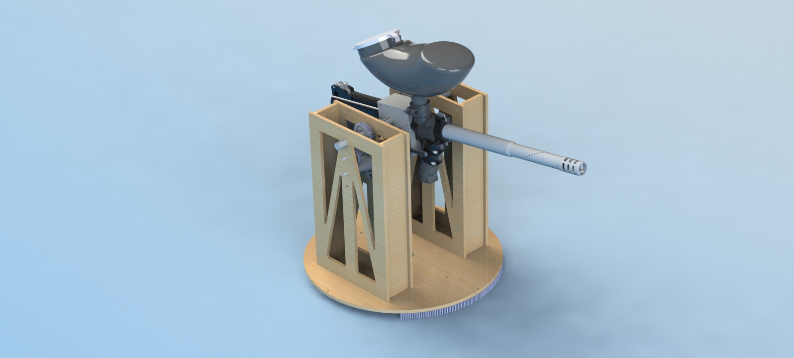
The Full Mechanical System
