Electrical System
Throughout our work on Project Pop Pop Pop, the primary goals of our electrical subsystem design were to reduce risk of personal or property damage and to prevent dangerous accidents. To this end, we integrated multiple layers of protection throughout a unified safety system.
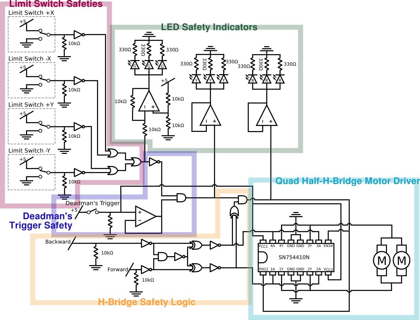
Our electrical subsystem has three distinct layers of safety: limit switches, a dead man switch, and a set of H-bridge-protecting logic gates.The limit switch safeties are placed such that a limit switch will trigger and inhibit system functionality as soon as the marker begins to move out of its acceptable range. The dead man switch, seen in dark blue above, allows us to separate power used for moving the trigger motors from the rest of the circuit. The H-Bridge protection circuitry, seen in yellow, ensures that two high signals can not be simultaneously sent to the quad half H-Bridge chip, protecting the system from dangerous shorts. If the limit switches, dead man trigger, and H-Bridge protection all register high signals, then the quad half H-Bridge (seen in cyan) is enabled. Upon receiving either a forwards or a backwards command, the H-Bridge powers the two trigger motors with approximately 1.5 amps at 5 volts.
A series of colored LED lights - as seen above in green - illustrate the state of the system. Green lights indicate that the dead man switch and all limit switches are clear. If the limit switches are clear and the dead man switch is compressed, the yellow LEDs also light up. Finally, if the limit switches are clear, the dead man switch is down, and the trigger motors are powered, the red LEDs illuminate. These indicator lights ensure that the operators of the system are aware of its operational safety state.
Limit Switch Safeties
The limit switch safeties address two potential safety failure modes. First, if the paintball marker is driven past a safe operational angle in either the pan or the tilt direction, the H-Bridge is inhibited such that the marker cannot fire. Secondly, if any of the limit switches ever become disconnected from the circuit (e.g. from a violent movement of the supporting shelving unit), the pull-down resistors inhibit the H-Bridge’s operation. The four limit switch signals are passed through successive OR gates after being inverted to provide a signal for the LED safety indicators and the dead man switch.
Dead Man Switch Safety
The dead man switch in our system primarily serves as an on button for power flowing to the dual half H-Bridge. Its secondary function is to provide a warning signal that alerts bystanders and operators that the system is armed and ready to fire. Our circuit provides power directly to the dual half H-Bridge, then buffers with a pulldown resistor to provide a logic signal to an AND gate. The output of this AND gate - which combines the dead man switch safety and the limit switch safeties - provides the yellow signal to our LED safety indicators.
H-Bridge Safety Logic
One significant risk from both a safety and reliability perspective was the possibility of shorting the H-Bridge used to drive the trigger motors by accidentally driving both inputs to the H-Bridge high. We resolved this issue by buffering the incoming signals through a small logical network, which never allows short-causing inputs to the H-Bridge. Additionally, the system’s two signal output wires are rigged through an XOR gate and an AND gate to provide the last LED safety indicator of active motor engagement.
Quad Half H-Bridge
The greatest challenge in the electrical section of this project was creating the drivers necessary to provide our motors with at least 1.2 amps across 5 volts. We developed several distinct topologies using discrete components. A full H-Bridge using Darlington topology BJTs was observed to fire the trigger in one test, but was unable to move it the next day. After a long and fruitless search, we finally found the SN754410N Quad Half H-Bridge in the Olin EE stockroom. It was able to push / pull up to 1 amp per half H-Bridge, making it more than sufficiently strong for our purposes. Additionally, it used a Darlington and Pseudo Darlington topology, which we had had previous success with. To our delight, we were completely successful in implementing this new chip, which works to specifications and seems to draw less power in waste heat than its predecessors did. This is the chip powering the trigger in all videos found on this site.
LED Safety Indicators
All the safety systems in the world are no good if the operators of the potentially dangerous machinery are not aware of which features are engaged at what times. To keep ourselves up to date on our system’s operation, we installed three sets of colored LEDs on the podium. The LEDs allow operators and bystanders alike to observe increasing levels of functionality and potential danger as power is delivered closer and closer to the quad half H-Bridge, and subsequently used to fire the trigger. Although this part of the circuit was not remarkable in any electrical sense, it allows important information from the full array of safeties implemented throughout our electrical system to be conveyed sufficiently to the operator and any bystanders, and is thus a crucial element of our electronic design.