PONG BOT - First Iteration
Mechanical Design
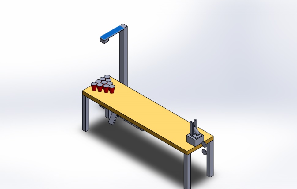
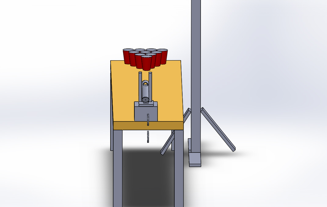
Our first design of the Pongbot uses a spring and pulley system to release the ball at a given velocity and pitch angle. We could control the pitch angle by turning a servo that controls the pitch, and we could control the end velocity of the ball by pulling the spring back a variable amount. We also decided that it would be optimal. Some of the problems of this system are the excessive need of pulleys and the inefficiencies due to friction. We also didn't factor in how we could effectively add a pan mechanism to this system. Thirdly, we couldn't have the robot play against an opponent because the robot is in a place where cups should be.
Electrical Design
Our Electrical Design team worked on helping the Mechanical Design team design a successful design that works with the electrical power that we plan on using as well as thinking about the requirements necessary in order to veritably control our system.
Software Design
We decided to build the software and firmware of our project on the same platform. We then had to decide between Python and MATLAB. We decided to use MATLAB because it had better and easier to use libraries to deal with both OpenCV as well as Arduino. OpenCV is a tool that allows you to create outlines of objects based on the colors of a photo. The computing team then each wrote three separate MATLAB functions: one function called openCV.m takes a picture and finds the centers of all the cups that it sees, and outputs the distance between the robot and the cup of interest; the second function called Toss.m simulates the flight path of the ping pong ball assuming air friction is present given the initial velocity and pitch angle; the third function is VelocityFunc.m runs Toss.m until it finds the optimal initial velocity and pitch angle for shooting the ball into the distance given by openCV.m. However, we did not include any integration between the systems nor any direct control of the Arduino.
PONG BOT - Second Iteration
Mechanical Design
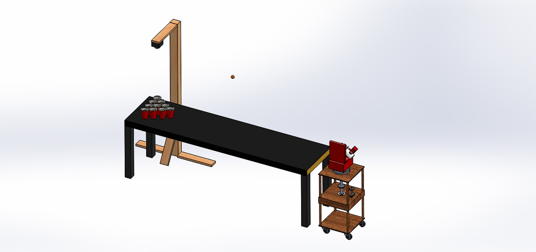
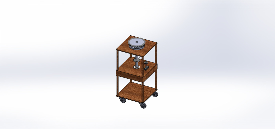
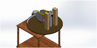
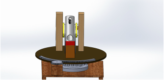
We decided to abandon the idea of the spring and pulley, for reasons noted above, and switched to a baseball pitching machine style of launch. The reason for this is because baseball pitching machines are very accurate in both direction and speed, and we wanted the exact same attributes in our robot. However, this did have one problem, which is delivery. We added a linear actuator as shown in Figure 1 above to solve this arising problem. We also added a lazy susan in order to be able to turn the system, allowing us to have pan. We decided to use a gear and gear-belt mechanism to turn the pan below the system, using a Servo motor. We also bought a rolling cabinet to place the entire system on so that it is completely separate from the water pong table. Problems arose in both systems. We had inconsistency in our launching mechanism because our delivery was wobbly. Our pan mechanism was too heavy and the Servo could not turn the system.
Electrical Design
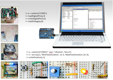
The Electrical Design team bought and characterized motors for the Pan and Linear Actuator systems, as well as wrote Arduino code to run all of the motors in the system.
Software Design
The Software Design team took the Arduino Code that the Electrical Team wrote and put it into a script. We then added calls to the three of the previous MATLAB functions into the script, therefore integrating the entire system.
PONG BOT -Third Iteration ( Final Design)
Mechanical Design
The Mechanical Team's focus on this iteration was to improve consistency across the board. The first job was to make the linear actuator double sided, therefore making it much more consistent. The Mechanical Team also added a gear rack directly on the large circle in order for a motor on the cabinet (and not beneath it) to turn it with ease. The Electrical Team calculated that a gear ratio of 1:6 would be optimal, and the Mechanical Team made a gear and rack at 1:6. By this stage, there was a standard deviation on any given shot of approximately 2 to 3 cups. The Mechanical Team then made a much more rigid design as well as making a smaller pipe such that the ball can jiggle less inside. This led to our current accuracy of a standard deviation of 1 cup accuracy.
Electrical Design
The Electrical bought and characterized a stepper to be used for the Pan Mechanism. They chose a stepper instead of a servo because it will have more torque and therefore be able to do the job better. They then computed the necessary torque as 1:6, and wrote Arduino Code to control the Pan Angle by telling the stepper to go a number of steps.
Software Design
The Software Design team added the Stepper Code written by the Electrical Team, and then also worked on improving detection of cups.
ELECTRICAL DESIGN
DC Motor-Controlling Arduino Circuit
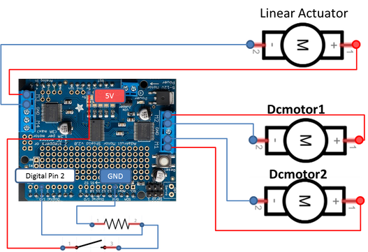 Figure 7. Circuit Diagram for the Pitching Motor and Linear Actuator Control
The Geared DC Motors is connected to Linear Actuator, which lifts the ball to the top part of the canon where wheels are located, so that ball can be launched by those wheels.
Two Ungeared DC Motors shown in the bottom right of circuit diagram ( DCmotor1, DCmotor2 ) are connected to 2 wheels and make them rotate at a calculated angular speed.
Stepper-Controlling Arduino Circuit
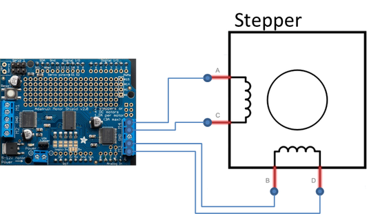 Figure 8: Circuit Diagram for the stepper motor for the pan mechanism.
The stepper motor is connected to the Arduino via the connections shown to the left. Since it is geared 1:6, it can turn .3 degrees per step.
SOFTWARE DESIGN
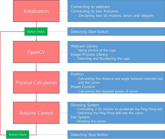
We used MATLAB to perform the PONG BOT because MATLAB gives us easy solutions (libraries) for webcam usage and image processing and Arduino control. To detect cups and balls and to calculate the distance between them, we used circle detecting function by color in MATLAB library. The button works as ON/OFF button. Once we push the button, the whole program will start running, and once we push it again, the process will stop until we push it once more to restart.
The conceptual algorithm
You can download our source code here.
