Subsystems
Each of our subsystems played a vital role in our final project, and were integrated into a complete system described in our World News page.
Mechanical
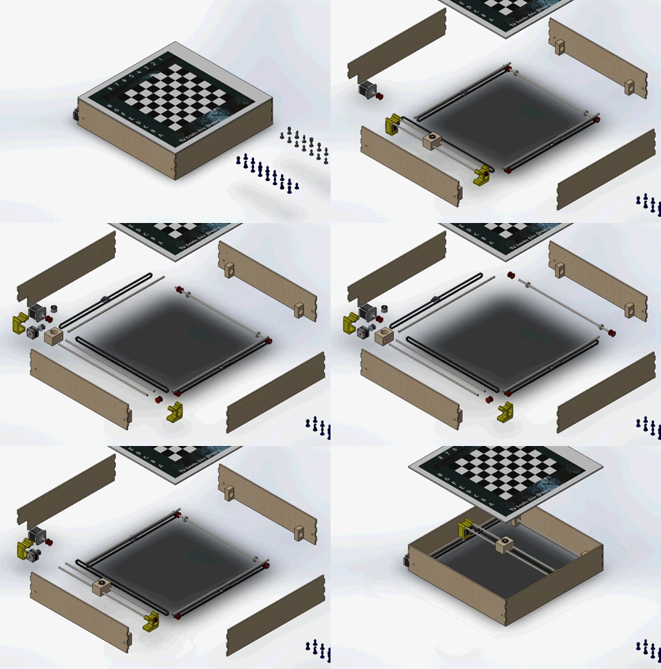

The purpose of the mechanical system was to move the electromagnet under the board. We used a 2-axis, belt-driven gantry system. We used stepper motors to run the gantry, because using stepper motors allowed for a higher level of precision and decreased the need for feedback control.
The electromagnet was settled in a small carriage made of wood. This wood carriage is connected to a timing belt, pulled by a toothed gear on a stepper motor. This subsystem allows the electromagnet to be moved along one axis.
Each yellow carriage in the one-axis subsystem rides along a fixed rail. As shown in the open-boxed render, each second-axis carriage is attached to a timing belt, driven by a large stepper motor. In order to make both carriages move at the same rate, we drove the second-axis belts together. One pulley on each side was press fit and connected to a free-spinning rod, which kept the belts in sync, as shown in the belt-and-pulley render.
Together, these two axes of motion allows for motion all over the board. Though we primarily used linear motion, either in one direction at a time, or diagonally, motion in any direction is possible, as shown in the circular motion video.
We had been having issues where the motor was skipping steps at high speeds. This problem was corrected by decreasing the speed of motion and adding lubrication on the rods in the form of graphite from a regular pencil.
Electrical
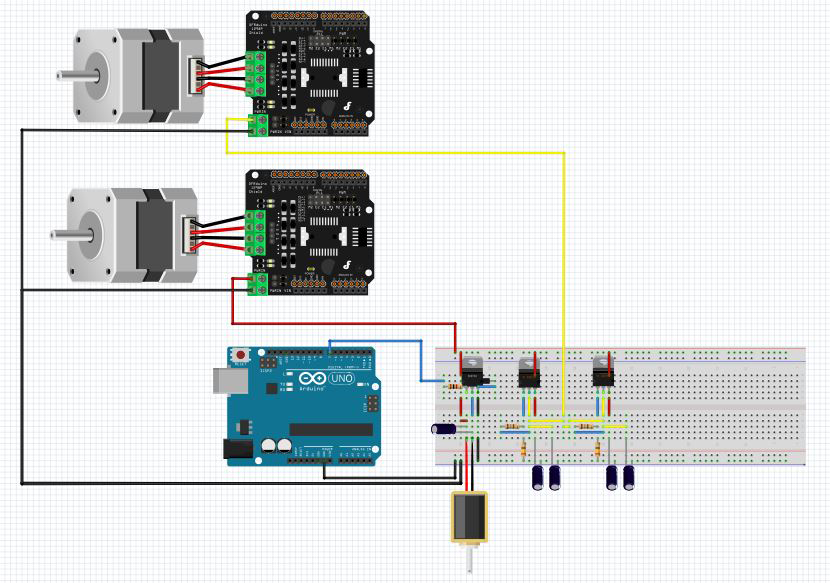
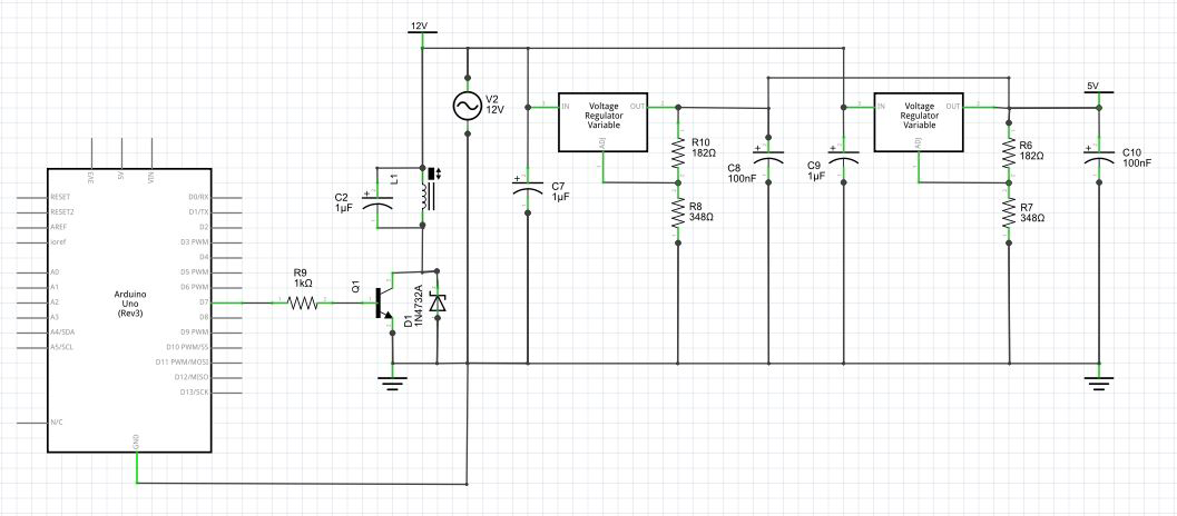
The primary goal of the electrical system was to allow communication between the mechanical system (location of the pieces and gantry) and the software system (signals that tell the pieces where to move).To interface with the physical system, two motors and an electromagnet were used, and to interface with the software system and Arduino and motor shields were used. A transistor was used to control the electromagnet with the Arduino and a voltage regulator was used to power the motors correctly from the 12 V power source. The software system sends signals to turn the electromagnet on/off or move the motor are sent to the Arudino, which then turns a pin on or off for the electromagnet, and sends pulses to the stepper motors to turn them the number of steps commanded in the dirction commanded.
The full circuit diagram shows the Arduino, transducer, electromagnet, and voltage regulator. Note that motor shields are not shown for simplicity, but plug in on top of the Arduino and connect to the motors and power sources as shown in the upper image. Additionally, twin voltage regulator systems were created to source the 3V, 2A needed for the larger motor. No regulation was needed from the power source for the smaller motor of the magnet, each of which operated at 12V and 0.33 A.
Data sheets: electromagnet, large motor, small motor, motor shields.
Firmware

The purpose of the firmware was to allow the control and game model to communicate with the electrical, and thus physical system. Our firmware was an Arduino code which translated electromagnet on/off signals and motor steps in given directions into electrical commands that controlled those two systems. An Arduino pin controlled a transducer which operated the magnet, and was commanded to turn on/off as necessary to move pieces. For the motor, the software inputted number of steps and direction for each motor, which was then converted into pulses to the two coils of the stepper motor that caused it to move as commanded.
All code for the project can be found at: https://github.com/hpelletier/WizardsChess.git.
Software
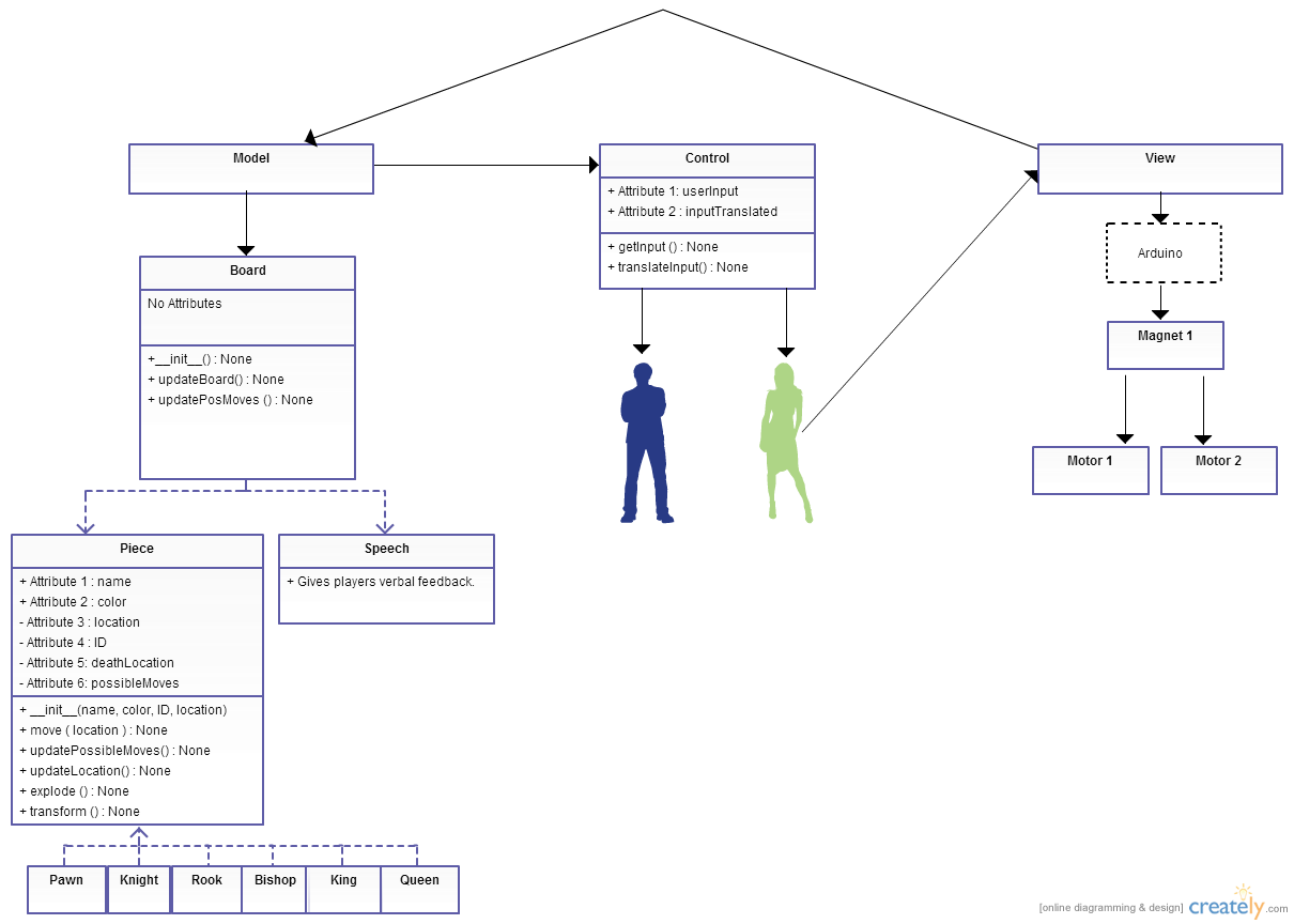
Our software system implements the model-view-controller architectural pattern, which allows us to easily handle user input.
The Main class imports the Model, View and Controller classes, and handles the interactions between them. The Controller class listens to voice commands from the player, interprets these commands, and sends them to the Model in the correct format. The Model class imports all of the piece classes (Pawn, Bishop, Knight, Rook, Queen, and King – each inheriting from the general Piece class). It implements the game logic (the rules of chess), keeps a virtual representation of the board, updates piece locations, and sends location information to the View class. The View class takes this location information, converts it to commands that can be interpreted by the Arduino, and sends the commands to the Arduino via the Serial port. The Arduino then controls the electromagnet and the motors in order to move the pieces on the physical board (covered in more detail in the firmware section). Upon seeing the updated board, the player decides on the move they want to make and speaks their command, starting the cycle over again.
External dependencies:
All code for the project can be found at: https://github.com/hpelletier/WizardsChess.git.
