The diode signals are read by the Teensy. We utilize a threshold to determine if the diode has a laser present on the diode or not. When the laser is present on the diode, we set a flag equal to 0 (if not detected) or 1 (if detected) and multiply it against the oscillating signal. Another way to think of the flag is as an include/exclude term for the signals that should be included in the output. By doing this, we can consistently power the 555 timers. This reduces the number of pins we use and simplifies the code.
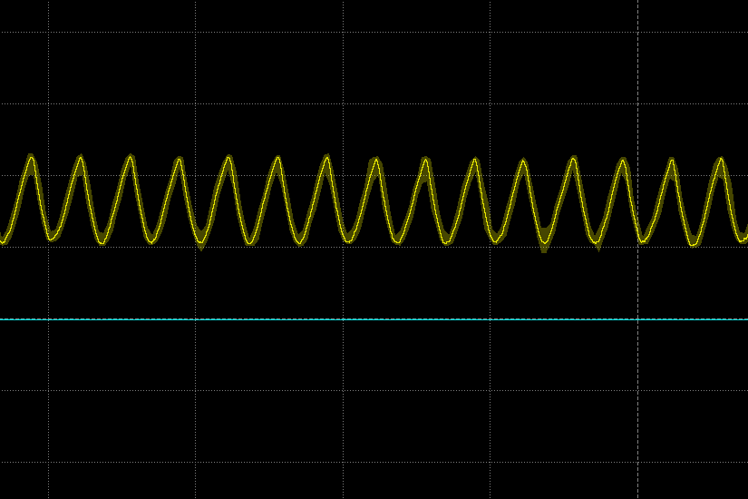
As we are combining waves, the sum of the output wave can achieve a level higher than the Teesny can output. Due to this, the wave will be clipped and not sound as we expect. In order to alleviate this issue, we scaled the output audio signal. To do this, we normalized it by dividing by the sum of the Diode flags, multiplied by a scale factor of 0.6, and further reduced by subtracting ~1.5 V from the signal. All of these modifications ensure the output signal can both be heard and is within the bounds.