Between Sprint 3 and Demo Day there was lots to finish up and tie together. Going into the final stretch, we had quite a to-do list:
|
Melody:
Implement a strain-gauge sensor to control volume and vibrato Add encoder button/knobs to adjust keys and octaves of each distance sensor |
Percussion:
Build full-scale drums Redesign cam/hammer drum Design and build lever system to disengage individual rhythm hammers |
Combine elements into a cohesive system:
Succinct, aesthetic design Mount that system as a rolling instrument |
In addition to all of these big-picture needs, there also remained the finishing touches: softening up the percussion sounds, decorating, wiring up all of the electrical components, and so much else.
To put it bluntly, things didn’t work out. But here are all the details that got it to be just about there
To put it bluntly, things didn’t work out. But here are all the details that got it to be just about there
Rolling Cart
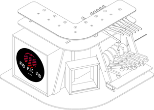
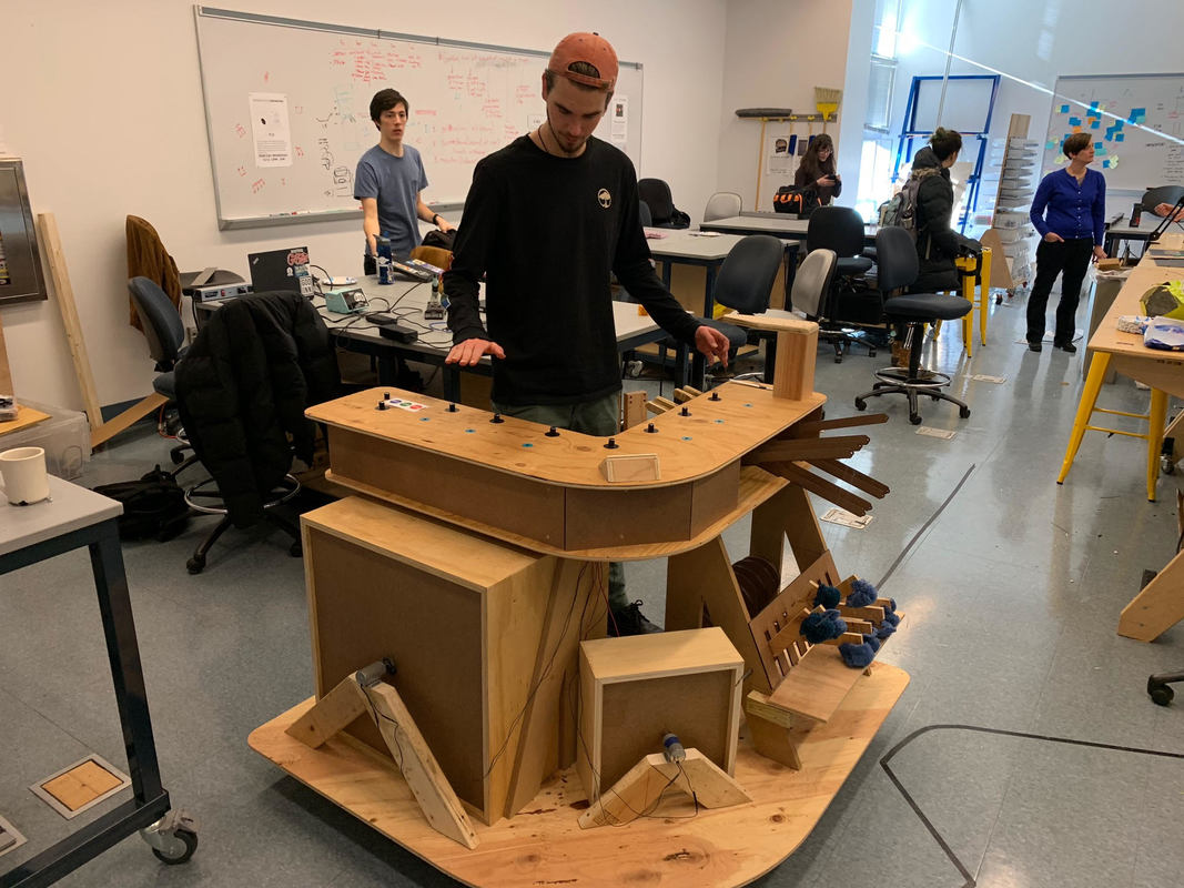
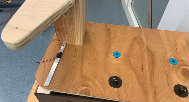
We designed the cart so that the whole system, including wheels, would be three feet tall, allowing people with a variety of heights to comfortably play all elements. The instrument wraps around the user at a square angle, reiterating this “semi-immersive” goal that we set in Sprint 1. Along the top surface is the spread of distance sensors, and at each edge are the string sensor and the drum/speed controls. Two of its four wheels lock, so that it can remain stationary when necessary, but rolls easily when it needs to be moved.
Refer to our CNC router cutsheet for dimensions and spacing. Remember that all of the rectangular slots are designed for the thickness of material that we used, so they will need to be resized if you choose not to use ¾” fibreboard.
Refer to our CNC router cutsheet for dimensions and spacing. Remember that all of the rectangular slots are designed for the thickness of material that we used, so they will need to be resized if you choose not to use ¾” fibreboard.
Solenoid Drums
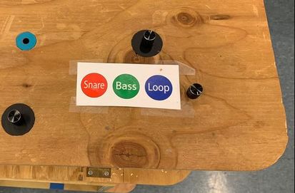
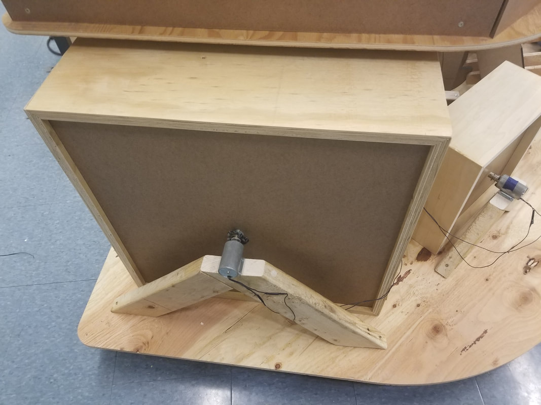
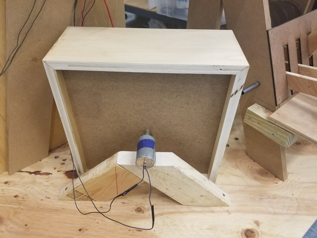
The solenoid drums needed to be redesigned to have a bigger, fuller sound. The snare drum is 14 inches by 14 inches wide and 6 inches deep. The drum head is set 1 inch into the drum’s depth. Its head also has some give so that it rattles like a real snare drum. The bass drum is 24 inches by 24 inches wide and 18 inches deep so that it sounds big. We also added a fabric “sock” to its solenoid in order to better distribute the force and add bass-y-ness to the drum’s sound.
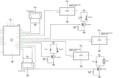
An Arduino controls the actuation of solenoids that are attached to the bass and snare drums. The solenoid shoots out when no power is applied, and recedes when power is applied. The arduino controls the solenoid by supplying a current to a transistor, opening the higher voltage circuit containing the solenoid. When the looping button is pressed, the arduino begins to record the loop. As the snare and bass drums are triggered, the arduino records the time in the rotation at which each drum’s button was pressed. Once the looping button is pressed a second time, the loop recording ends and the playback begins, repeating the drum pattern that was played during the loop recording. Whenever the rotation of the mechanical rhythm matches one of the recorded button presses, it plays that drum.
The motor’s position can be calculated with the encoders. It detects each change of 0.16 of a degree of the motor’s rotation. Thus, we detect when the camshaft has made a full rotation and can use the time this full rotation takes to determine the beats per minute played. This information determines the ‘beats’ we snap the beginnings and ends of solenoid drum loops to. For more information on how the encoder works, follow this link: https://www.pjrc.com/teensy/td_libs_Encoder.html.
Electronic Melody
|
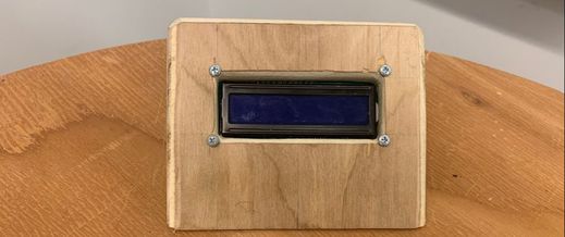
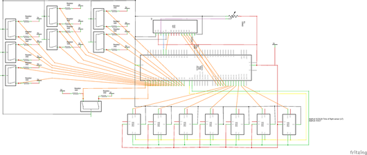
For the final design of the electronic melody, we set our sights pretty high. We added a rotary encoder and button for each sensor that could change the chord played with the turn of the dial. This made it so that it is even more customizable as each sensor can be a different chord of the user’s choosing. We also added a Liquid Crystal Display that would indicate which instrument or chord is being selected, as well as which note is being played at the time. |
Each sensor is a time of flight sensor that senses how far away an object is straight above it. The user can play a chord by putting their hand over the corresponding sensor. The height of their hand changes the octave at which the chord is being played. They can then change the chord of each sensor by pressing the button next to it, and turning the rotary encoder next to it, then when the chord they want is displayed on the LCD, pressing the button again. They can also perform the same action with another rotary encoder and button to change the type of instrument they want to play. There is a strain gauge on the final construction of the P.I.E., but we were not able to electronically implement it in time. It would have controlled the volume of the sound.
Hammer Drums
|
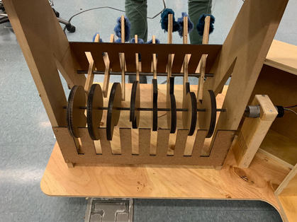
On the left side is a percussion system to provide a simple but malleable background rhythm. The system consists of a motor-driven camshaft with eight shell-shaped cams, a static shaft with eight hammer-shaped drumstick arms, and a percussive board. The motor is connected to a knob on the top surface interface for the instrument-player to control its speed. The motor has a maximum speed of 3 revolutions per second, meaning that the instrument can play up to 180 bpm with all eight hammers engaged.
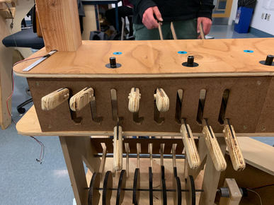
During the final weeks, we added a sophisticated engage/disengage interface for the cam-driven hammers. This design relies on a lever system mounted below the top layer of the final design. Lever handles extrude from j-shaped cutouts in a panel facing the user, and can rest in one of two positions: engaged, wherein the lever rests at the top of the cutout, and disengaged, wherein the lever rests in the lower upturn of the j. |
The levers rotate on an axle inside the main body panel, and extend nine inches past the edge of the upper level. At the end of each lever, a string extends down to a corresponding hammer on the camshaft system. Thus, in the disengaged position, the lever pulls up on the hammer so that the hammer cannot interact with its corresponding cam, and remains upright while the other engaged hammers go about their noise-making.
Since our previous iteration of the camshaft drum system was much too loud, we opted to also add ‘sock’ softeners made out of fabric scraps to the heads of each hammer, and substituted our previous long rectangular drum for the aforementioned percussive board. These changes not only made the system sound better, they also consolidated the design concisely, and in the case of the fuzzy socks, added a nice touch of color. |
In the end, we achieved a cohesively mounted structure, but somewhere in the integration process, we lost the functionality of the individual components we had successfully developed in earlier sprints. We believe our wiring may have been the breaking point for both the distance sensors and the looping functionality of the solenoid drums. We did not end up having enough time to debug these issues before our final demo, and so our instrument did not function as we had hoped on this day. But with just another week, we could fix these issues, regain the functionality we once had, and achieve the instrument of which we had once only dreamed.
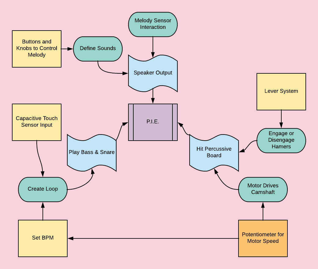
System Diagram
Source Code, CAD Images, and Circuit Diagrams
You can access all of our source code at https://github.com/nathanestill/NevNtheNevers. Our images page consists of all of our CAD designs and circuit diagrams used to create our final design and previous prototype.

