How (our) Laser Tag is Made
Fun fact! Laser tag doesn't actually shoot and collect hits with actual lasers (that'd be dangerous). Instead, to build a laser tag game, you use IR leds and IR sensors.
We're using TSOP4038 IR sensors. It has a wide range (a relative transmission distance up to 45 degrees - all directions but behind it- and 30 meters). It was interesting to find out that the sensor doesn't sense IR light waves by themselves, but change in frequency. There's a message comprised of ones and zeros encoded in wave (on/high and off/low). This message is transmitted in a carrier frequency, sort of a base frequency, and then a background frequency is transmitted - its a different frequency, and it represents a "rest". The carrier frequency for the TSOP4038 is 38 kHz. When it recieves the signal, the TSOP4038 gives a variable output in voltage, starting at its positive voltage input, and going down to zero, as the signal grows stronger.
How We Tested, Tried and Used It
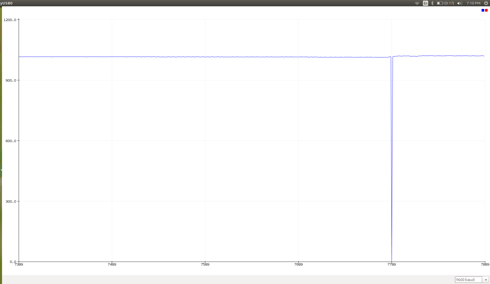
The first thing which we did was make sure the sensors and leds worked. First, we hooked up the leds to power and determined if they were working. Here's a tip: you can usually see IR light through a phone camera - except, some phone cameras now have IR filters, blocking the IR light! Most old phones don't have filters, though. Next, we hooked up the sensors to a different power source and to an Arduino. We set the PWM frequency, and used this code to visualize the output from the serial monitor :
- Serial.print("X: "); Serial.print(sensorValue1); Serial.print(" ");
- Serial.print("Y: "); Serial.print(sensorValue2); Serial.print(" ");
- Serial.println("uT");
From there, we faced a TV remote to the sensor and clicked the power button. From the serial monitor, we saw there was a response. We then tried shining the IR leds onto the sensor and got no response - here we had to go back and read up on what an IR sensor actually detects. We used the instructions from Zovirl Industries as a base, and modified the code to our needs.
We used this code, a sensor and an led to determine where our sensors and leds should be placed on our robots. Because of its wide range, we decided that we'd put two sensors on either side, and a variable amount of leds on the face.
To finally integrate the sensors and leds with our robots, we created Arduino code which executes different functions in response to the output of the sensors.