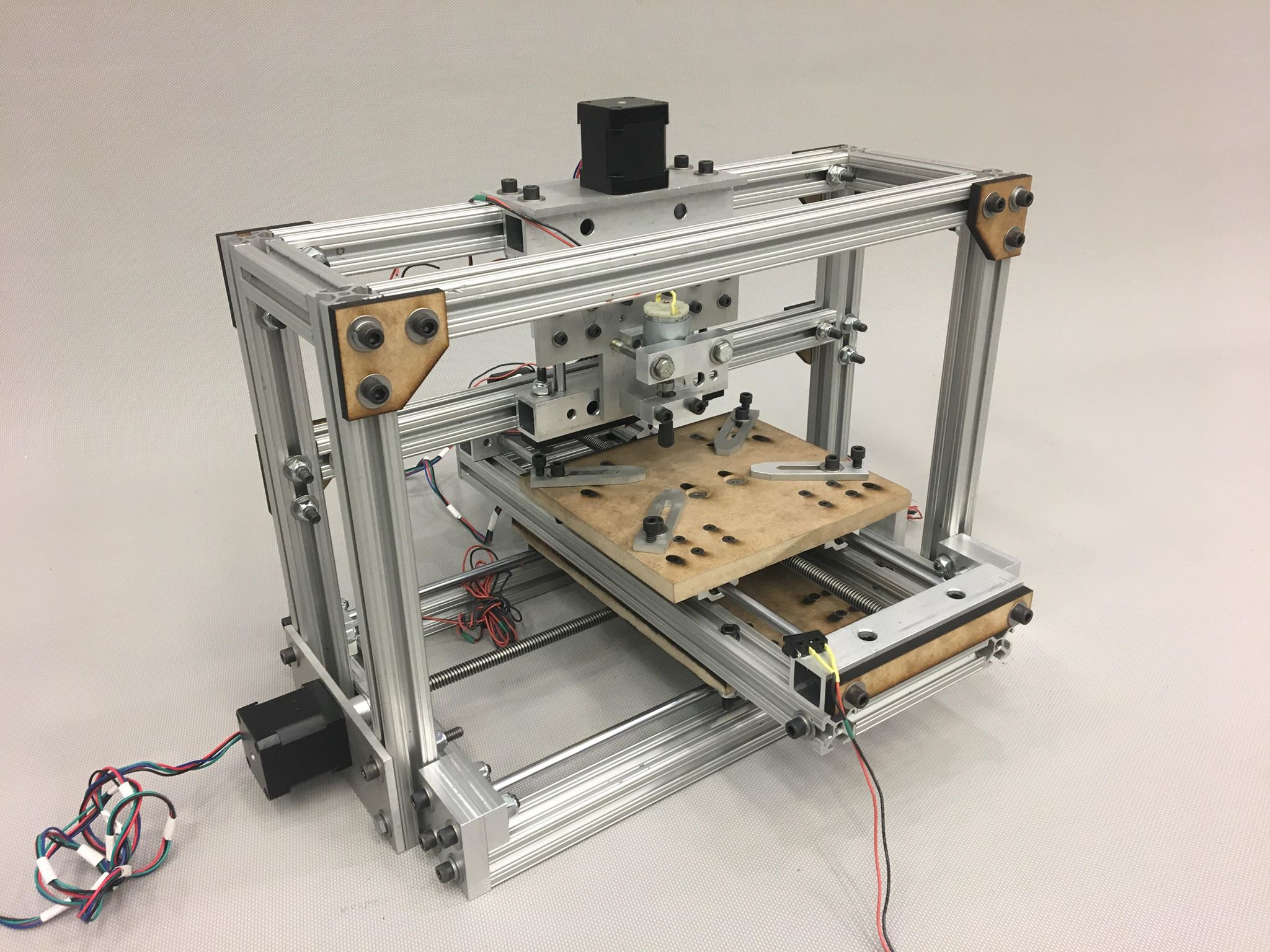
Final Design
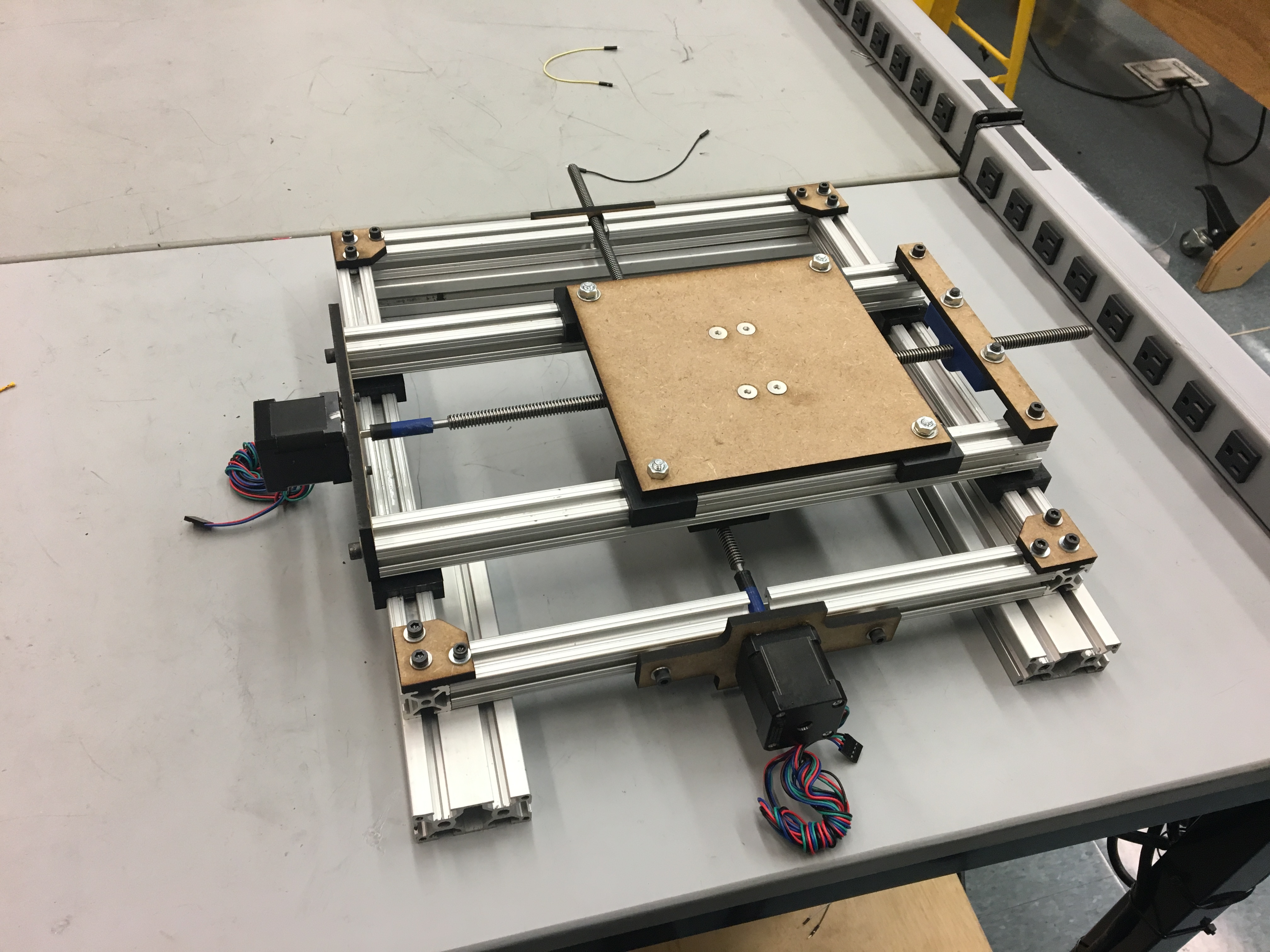
The robust compound table holds the workpiece and allows for accurate movement the X and Y axes. They slide along round ways using linear ball-bearings and are driven by lead-screws.
Frame
The table frame was made from 80/20 brand aluminum framing extrusions. This material was chosen due to the fact that there was ample 80/20 stock freely available to us in the lab, as well as because the form of the rods offered many fixturing options (and served as our linear motion rods in the first sprint). The bars were milled to length and tapped, with around 40 through holes drilled for the ¼-20 bolts that hold the table together. Laser cut brackets ensured that the corners remained square.
Work Holding
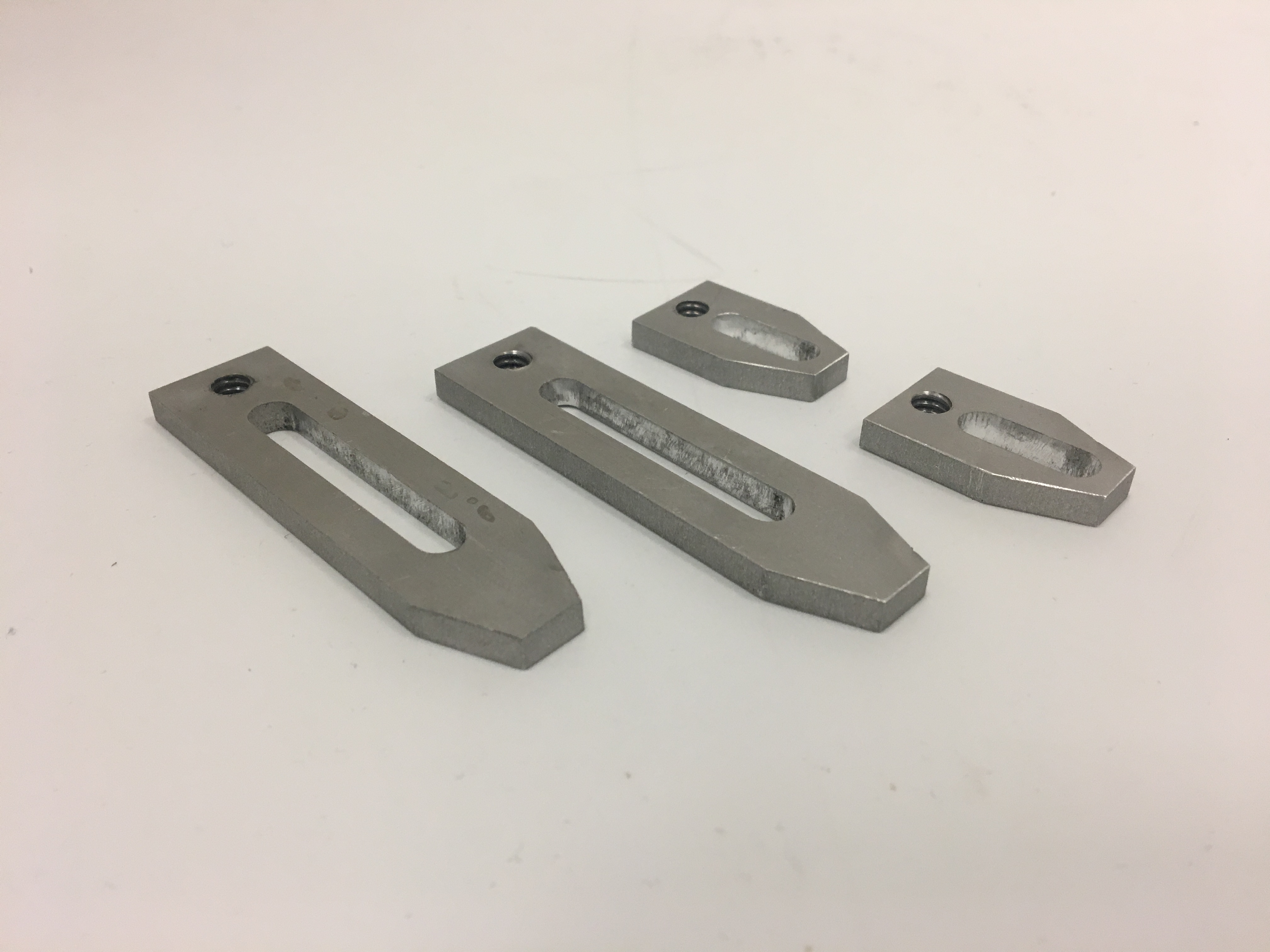
The platen is made from a piece of 0.5” MDF which was laser cut to ensure precision hole locations. It attaches to four linear bearings which proved to be much more rigid than two. Additionally, it has a total of four 0.25” holes for mounting adjustable toe clamps for securely fixturing the work pieces.
Lead Screw and Ways Assembly
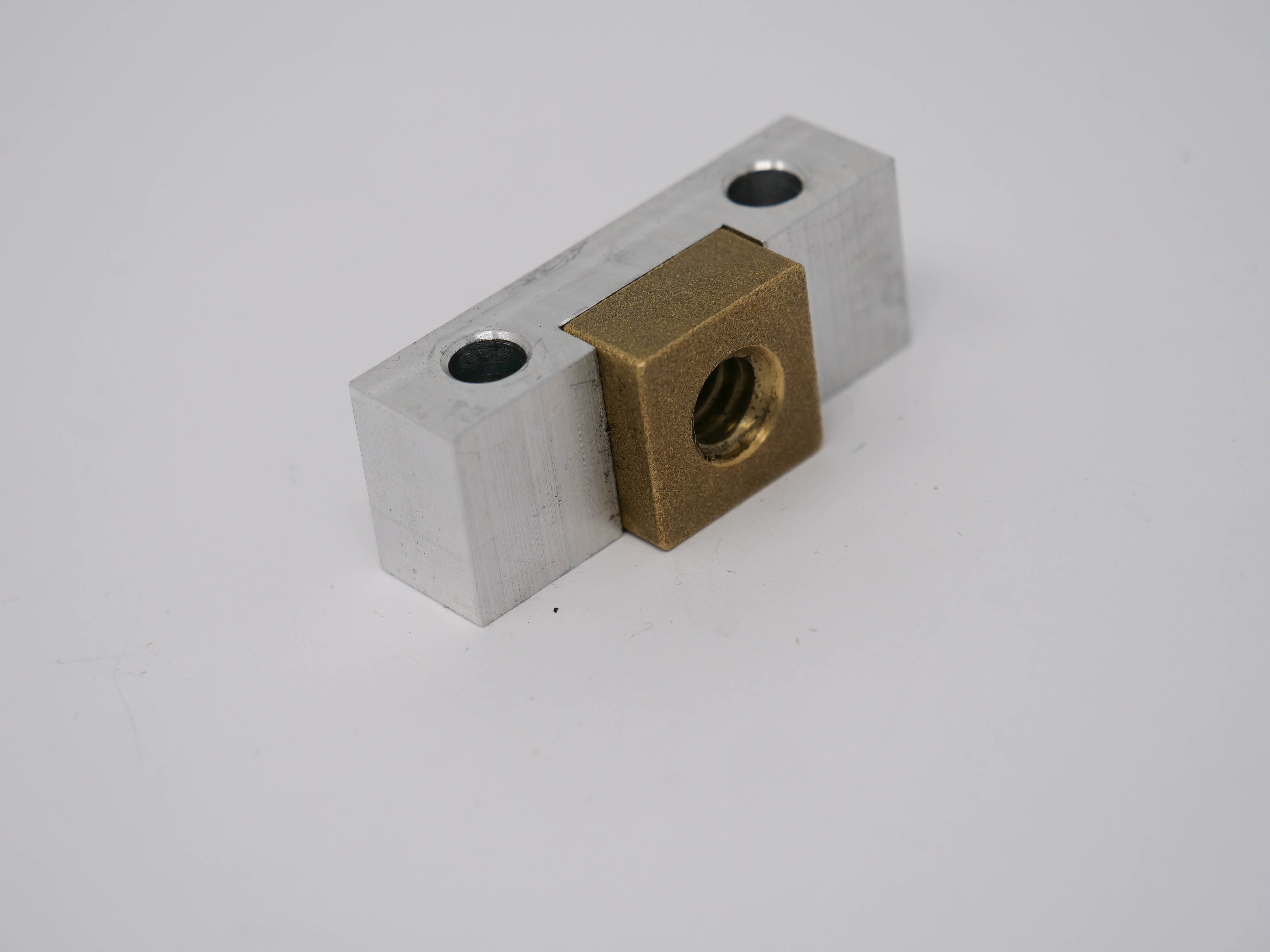
Each axis on the table is driven by a ⅜ -12 lead screw and nut. The square brass lead nuts are press-fit into slots in the milled aluminum lead nut holders which are attached to the platen and lower mounting plate with countersunk ¼-20 bolts to give a flat surface for workpiece clamping. The ways are 8mm case hardened stainless steel with matching linear ball-bearings and fit into 8mm reamed holes in the aluminum ways holders. The motor mounts are made from water-jet aluminum plate with counterbored holes to allow the cap head M3 screws to be flush for interference reasons.
Iterations
Sprint 1
The first iteration of the compound table had a wider footprint and used custom 3D printed sliders as linear bearings on the 8020 frame members. The lead-screw bushings, motor coupers, and a variety of other parts were 3D printed, and all of the flat components were laser-cut.
Sprint 2
In sprint 2, we switched to using 8mm rods and linear bearings from a 3D printer slide set. We also narrowed the footprint and added the frame for the z-axis. Some captive nuts/bolts were replaced with through-bolts.
Sprint 3

The platen and lower mounting plate were replaced with ½” MDF with countersunk M4 screws and laser-cut toe clamps were added for more secure work holding.
Final Push
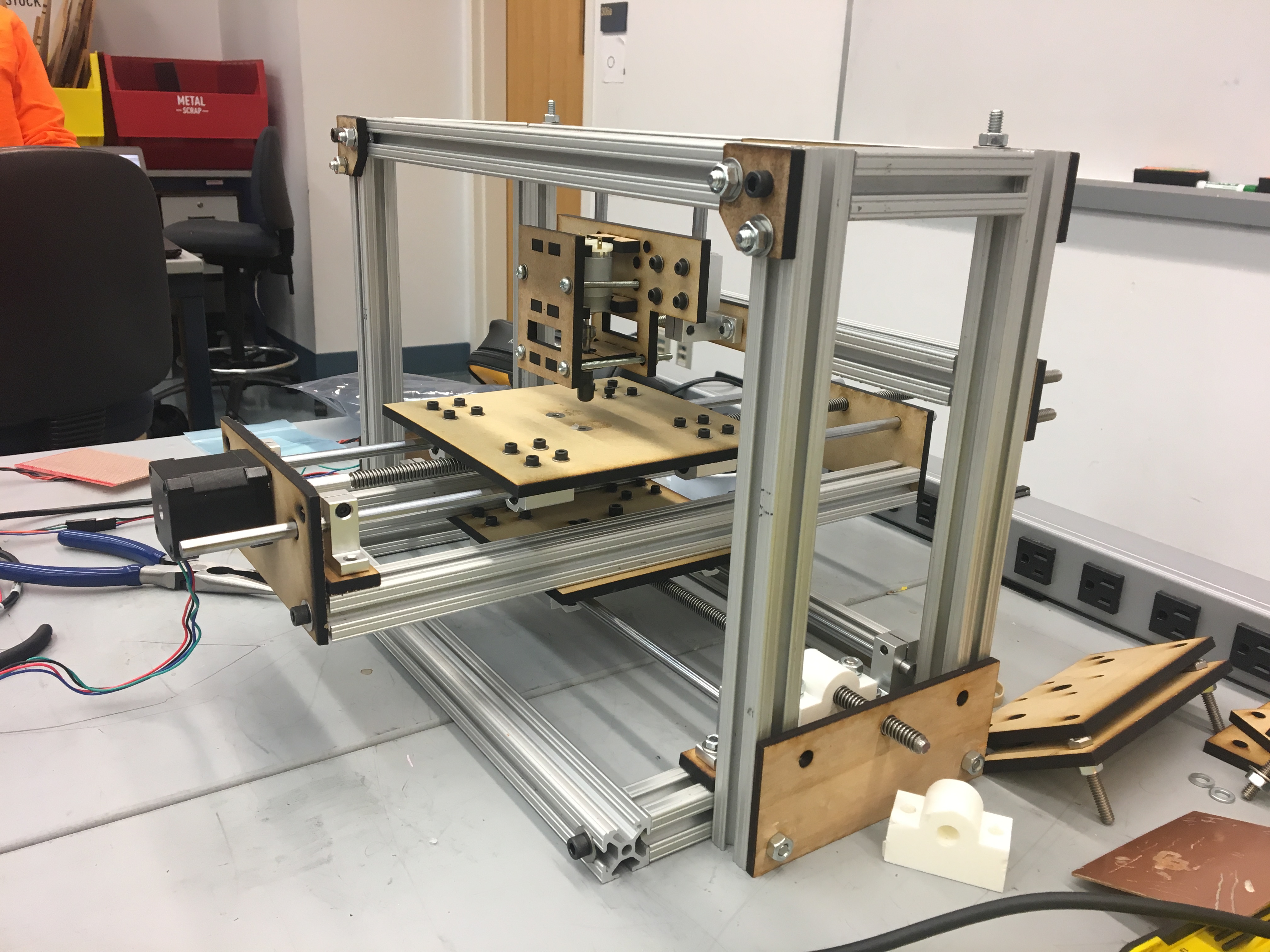
All motor/ways hardware was replaced with milled or waterjet aluminum plate for increased rigidity. Additionally, the x-axis ways were moved further apart to increase stability. We also drilled through holes to replace all captive bolts for precision and ease of assembly.