The electrical subsystem has two main parts: the real time control system and the user interface system. The real time control system is based on an Arduino Uno V3. The user interface system is a Rasberry Pi B+ with a LCDTFT touchscreen, a rotary encoder with two LEDs, and an emergency stop switch. The two systems via serial through a USB cable.
User Interface System
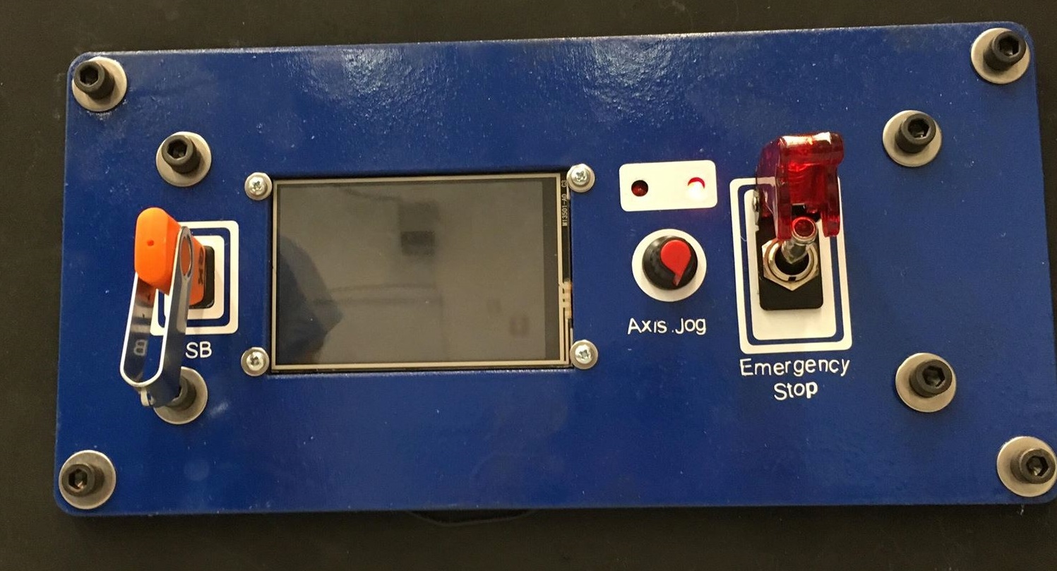
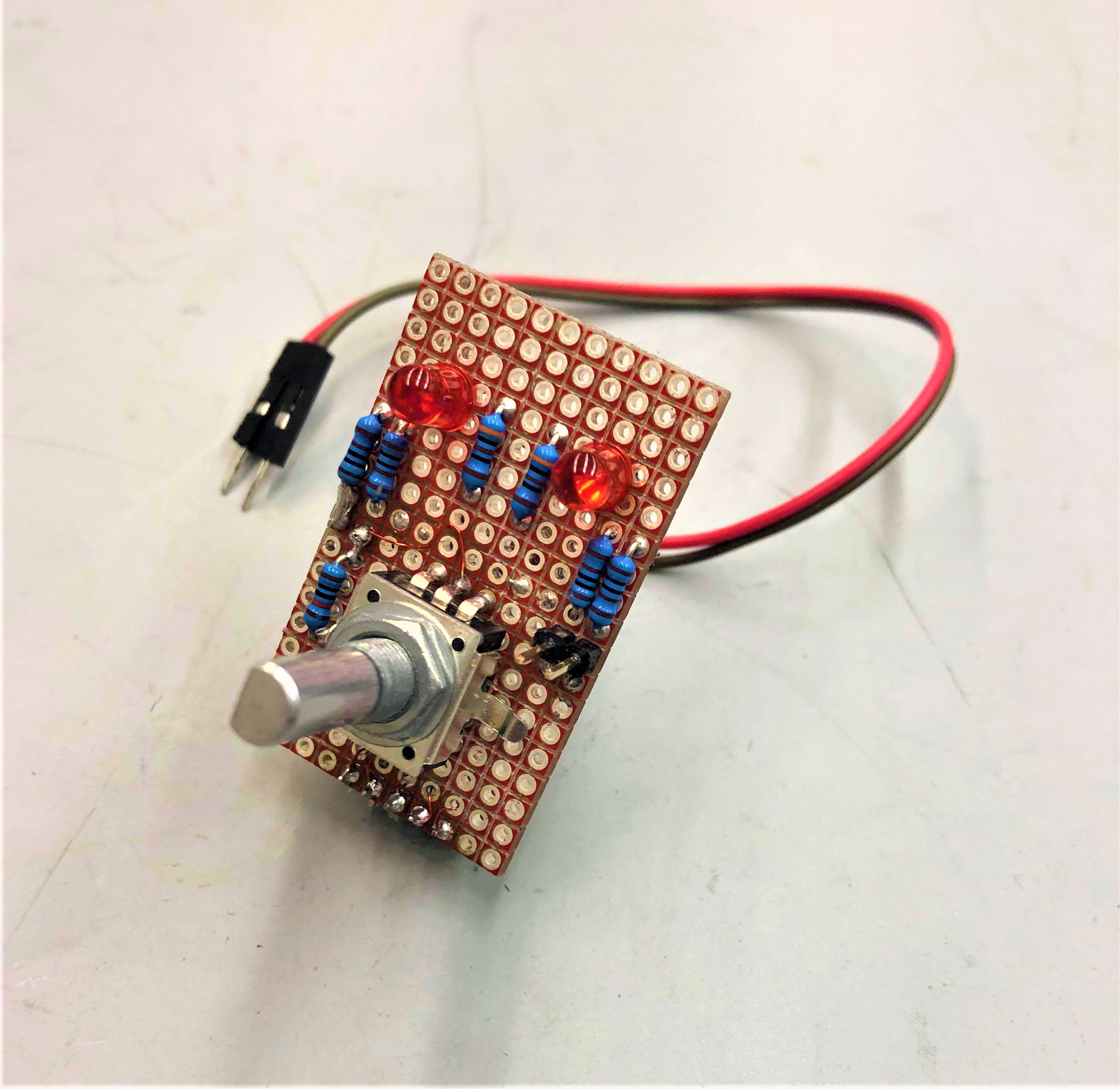
The quadrature encoder with pushbutton switch allows for manual axis adjustment for zeroing (the LEDs indicate which axis the encoder is controlling hte motion of), and the emergency stop cuts the power from every component except for the fan in case of a problematic situation.
Real Time Control System
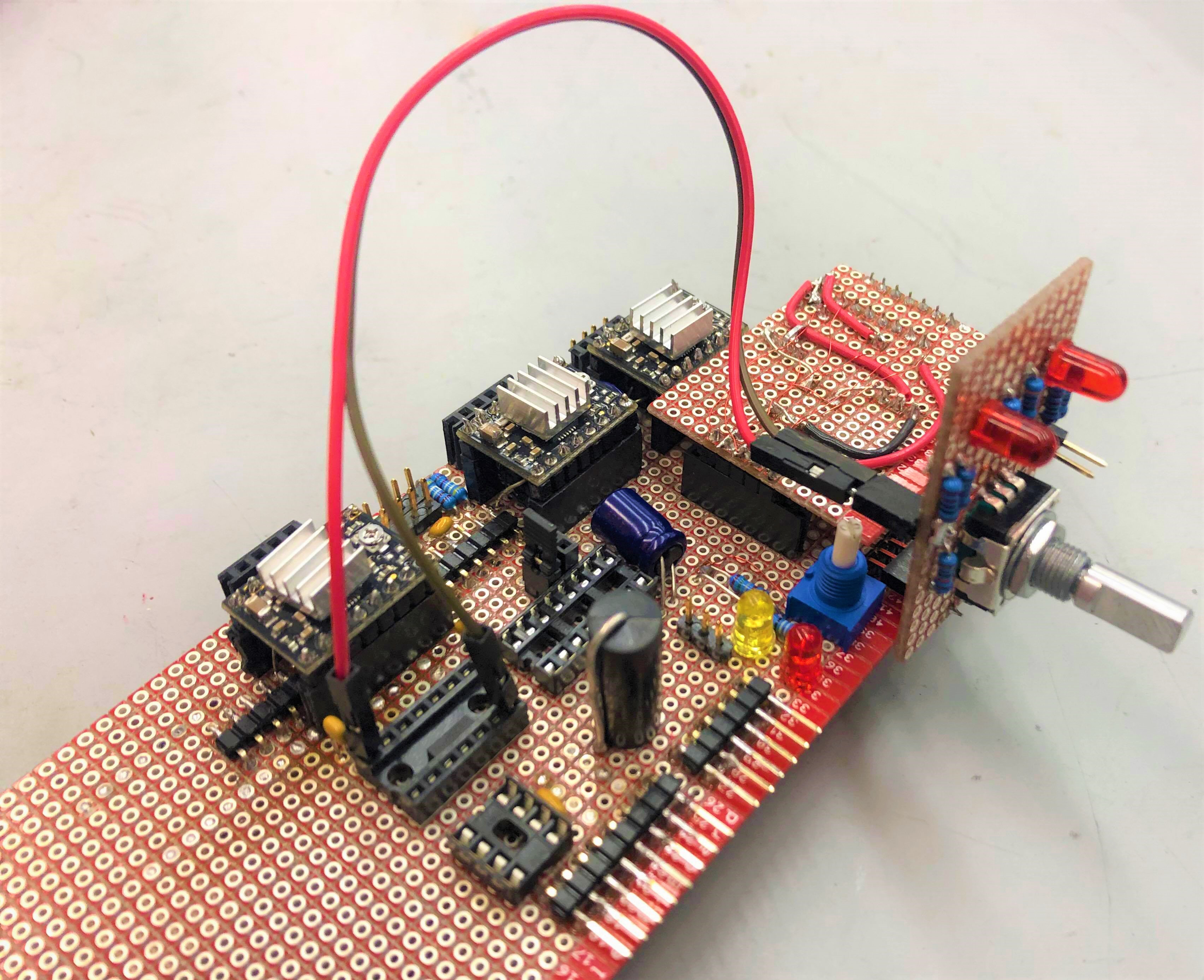
We chose to use an Arduino as our main real-time controller because it provides a fast method by which to achieve a viable product despite its limitations. Instead of purchasing a pre-designed Arduino shield which would limit our freedom while writing firmware and configuring our integration with mechanical systems, we (ironically) decided to create our own perforated protoboard that easily sits on top of an Arduino Uno similar to other Arduino shields. We also created two extension boards which connect to the main board for increased functionality and modularity. By doing so, we were able to both customize our electronics easily and leave room for future expansions as needed.
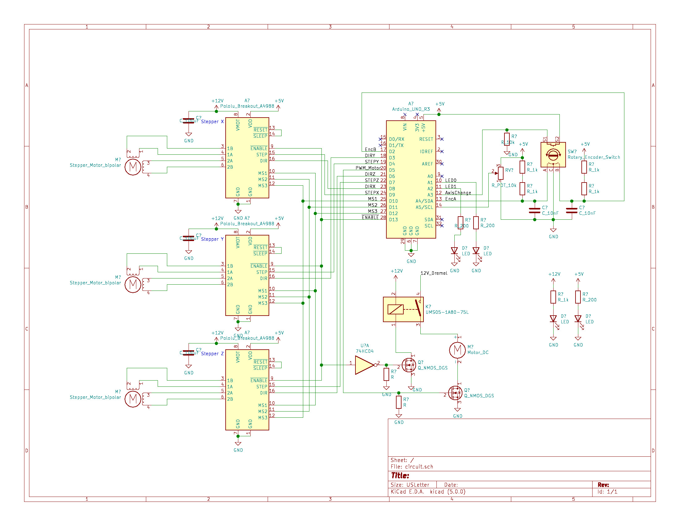
On the main board which sits directly on the Arduino, we have three A4988 stepper motor drivers (one for each axis) and connections to limit switches and the stepper motors themselves.
On the the first extension board sit two LEDs and a quadrature encoder switch. A press down on the quadrature encoder switch allows the user to cycle through between four modes with which to zero the axes prior to when the mill starts: Manual (motor drivers disengaged so users can turn the lead screw to move the axes), X, Y, and Z. The quadrature encoder ticks provides information on the distance and the direction the motor should be traveling in.
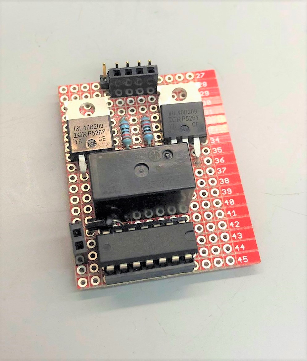
The second extension board has a power relay and a N-channel MOSFET to drive the z-axis spindle motor throughout the milling process. The power relay is separately controlled by the Arduino, ensuring the safe physical disconnect from a dangerous cutting tool from power when it is not enabled.
Power Management
The power distribution of our system is spilt between between the main control system and the z-axis actuation. Both are connected to a 12V wall adapter. The Raspberry Pi uses a 5V wall adapter, and it also powers the Arduino.
Thermal management is another important part of the electrical system because of the large amount of current that flows through the system to power the DC motor and three different stepper motors. Each stepper motor draws about 0.5A while the DC motor pulls about 1.3A. For passive heat dissipation, we placed heat sinks on all three A4988 stepper motor modules and we used a large through-hole N-MOSFET with a large heat conductive component. We also used a computer fan to circulate air actively across the electronics.