MECHANICAL
An Overview Of Our Project's Mechanical Component
First Sprint
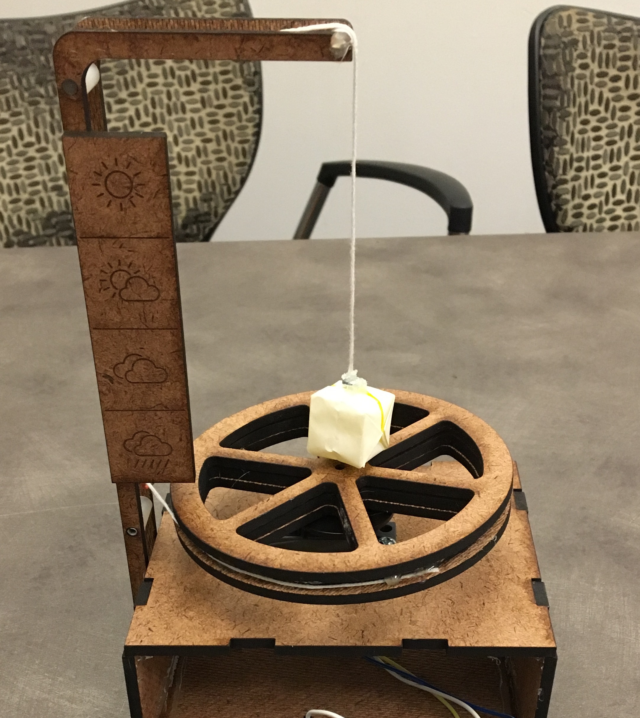
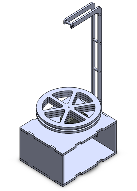
The main goal for our first sprint was to build a structure that enabled a wheel mounted on a servo to operate a pulley. There is a single pulley at the base of the structure. The 3-layer wheel is attached to the servo and dispenses thread. The wheel had to be this big because the servo only rotated 180 degrees, but we still needed about 4 inches of travel. The thread travels up and down the ladder, and a ball is suspended at the end at the highest point. The movement of the wheel pulls the ball up and down in midair, and the servo sits in a laser-cut piece of hardboard. The wiring goes through the hollow part of the hardboard “box” and is attached to the Arduino. This is a preliminary structure that would evolve into an array of many pulley systems.
Second Sprint
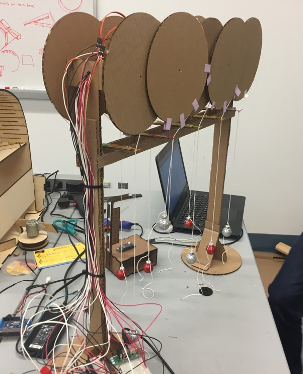
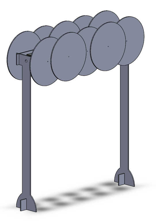
In our second iteration, the focus became on setting up a functional array of many motors. An array of 10 pulley systems was integrated; each rotating disc dispenses thread, and a ball is attached to the end of each thread. The movement of the rotating discs (which act as spools) pulls the balls up and down. The stand allows enough space for the balls to travel up and down to create a pattern that can be visualized. The wiring goes through the empty wiring channels in between the two rows of discs.
It was during this phase that we encountered a major setback—shipping. The H-bridge motor controllers for the DC motors that we ordered did not get here in time so we had to fall back on servos. We stuck with one of our other goals: that the motor array should be suspended and significantly larger than our first iteration. Thus we ended up with rapidly prototyped gigantic cardboard pulleys as shown since servo motors only had 180 degrees of travel. The stand for the motors were two supports on opposite ends made of cardboard.
Third Sprint
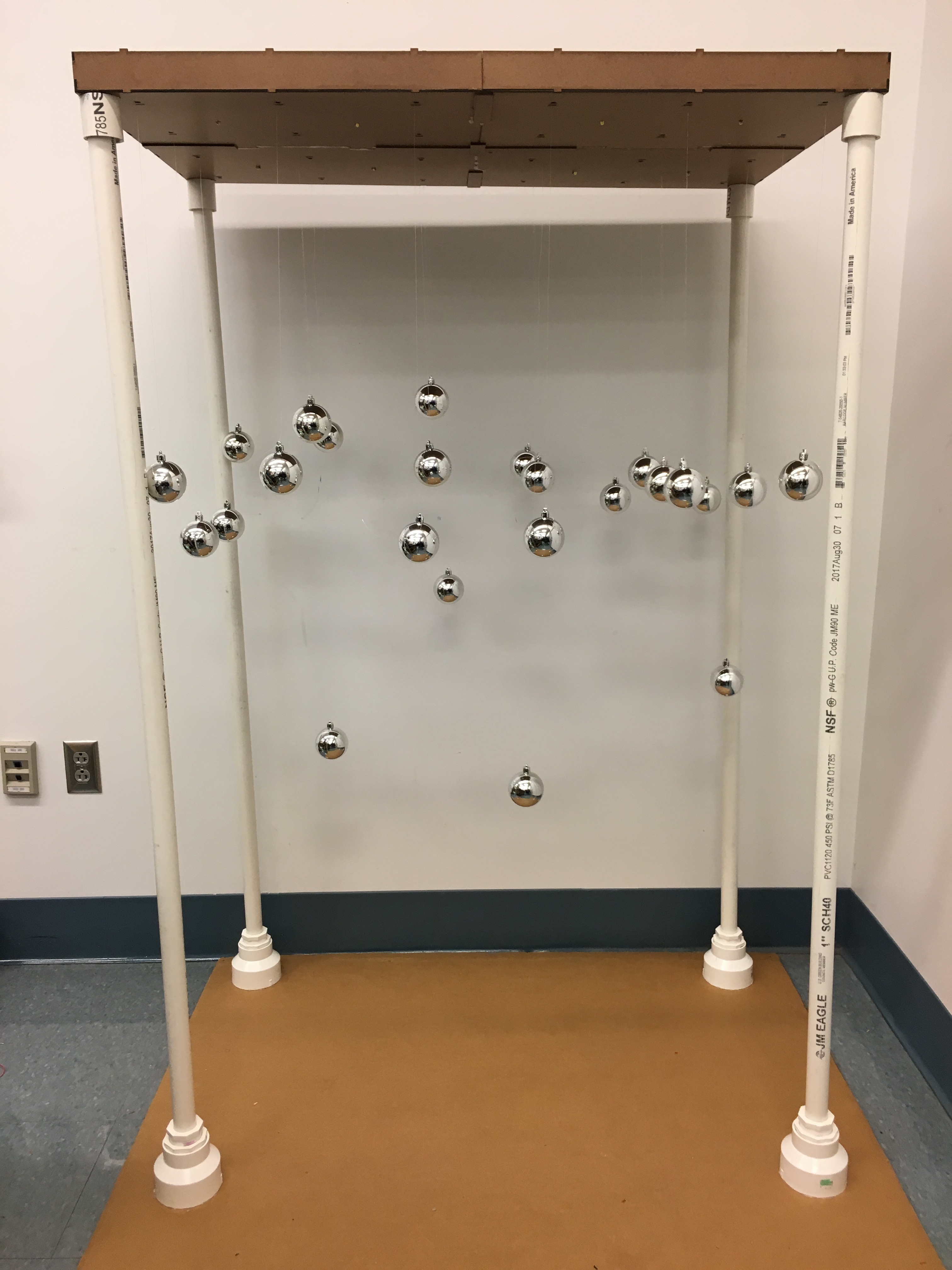
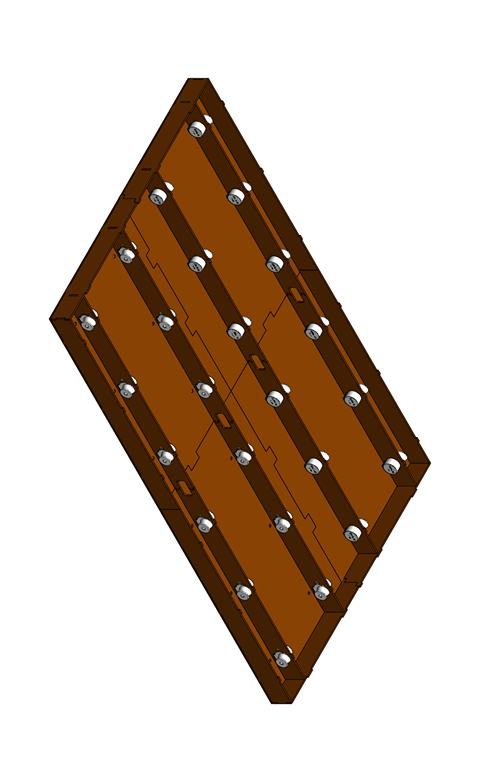
We implemented stepper motors during the third round, which was a huge change as we were able to cut the huge pulleys from servos. The new pulleys were much smaller and there design allowed them to center the wire and allow 3 inches of travel for rotations. We chose 3 inches of travels because it seemed like a good speed based on our previous iterations. We created a compact array of 24 motors using fishing wire and silver ornaments. We chose 24 motors because our budget could only afford three PCBs to control them. We throttled by the number of PCBs, however, we wish we could have done more. The stand consisted of 4 PVC pipes that elevated the top box, which was removable.
Our mechanical design greatly varied throughout our sprints finally resting on what was made in the third sprint. We are very happy with how it turned out. If you would like our CAD models or more information, contact us using the information on our About Us page.