Electrical
An Overview Of Our Project's Electrical Component
First Sprint
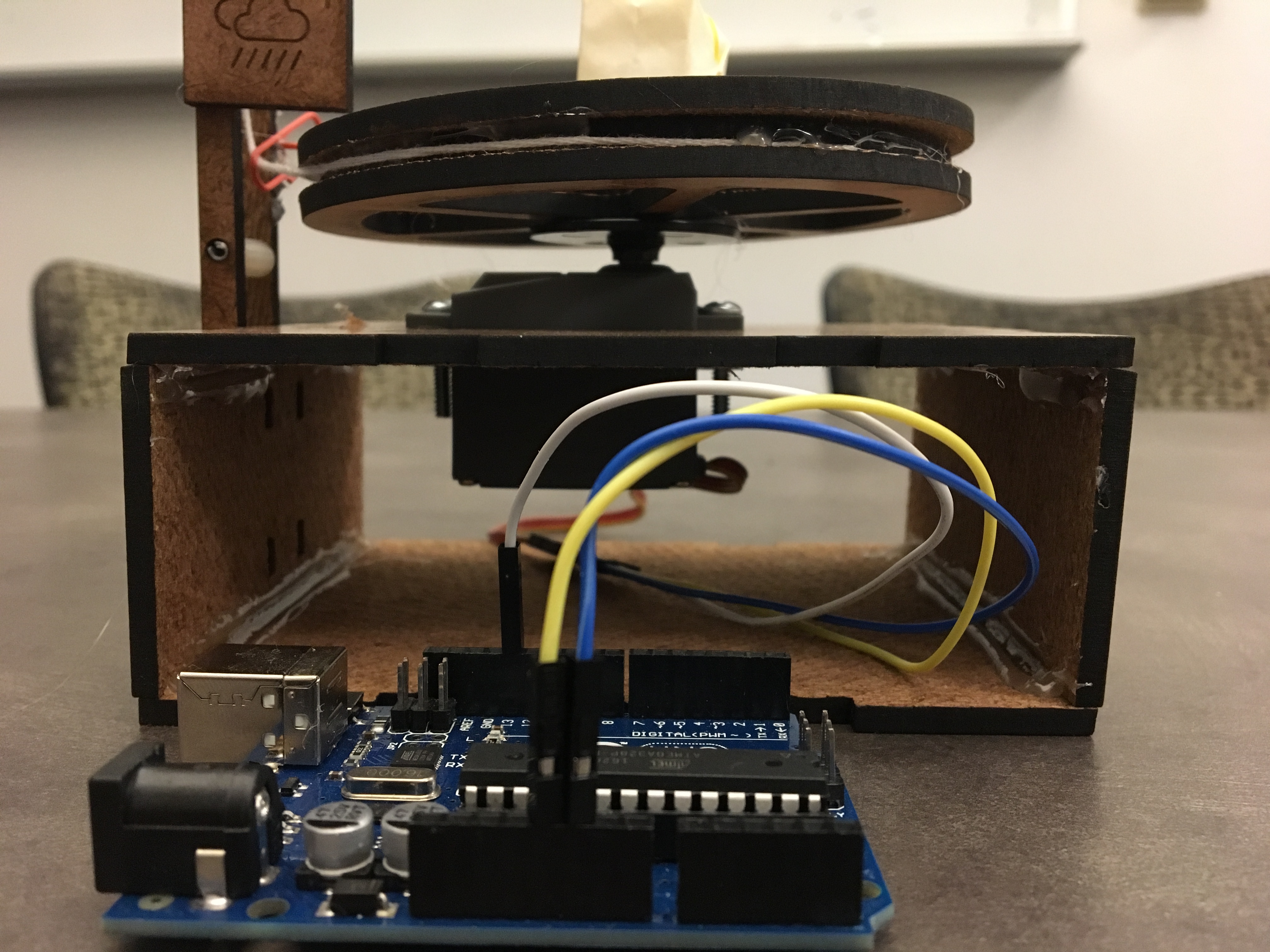
For the preliminary one-pulley design, the electrical components were pretty simple: we just needed to control our single servo with an Arduino.
Second Sprint
The second sprint presented a bit more of an interesting problem: we had to figure out how to control 10 motors simultaneously, this time with two Arduinos. Unsurprisingly, this required lots of wiring, and we realized that wiring would be a critical part of the final design. Initially, we had planned to electrically control our DC motors with H-bridge motor controllers, but this never happened due to shipping delays, and we pivoted back to using servos. Controlling servos still remained a fairly simple process; we just had to connect more of them to the Arduino.
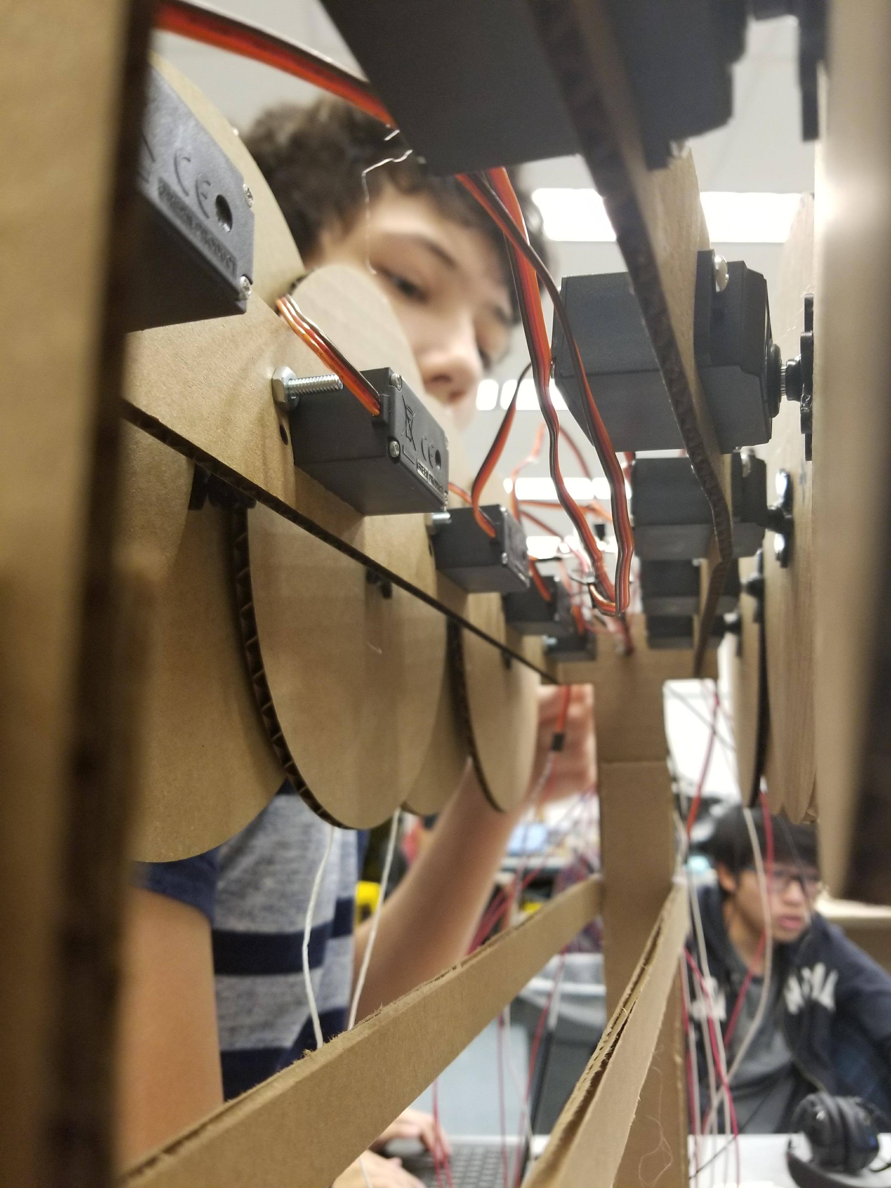
Third Sprint
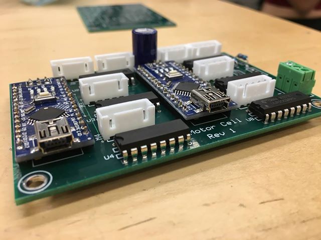
The third iteration was where the real challenge came in. We realized that if we wanted to control 24 stepper motors at once, we would need more power and many connections between the motors, their motor controller boards, and the Arduinos that would control them. We made a decision to design our own PCBs incorporating Arduino Nanos as slave modules controlled by one master Arduino Uno. On each circuit board, there were two slave modules each controlling four motors. With three circuit boards, there were six total slave modules controlling all 24 stepper motors.
Stepper Motors
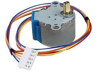
In order to precisely control each ball, we needed to be able to tell each ball's position. This could be done with the use of encoders with normal DC motors. However, each encoder would have to be individually calibrated, and with 24 of them, that task is not trivial. Our solution to this was to use stepper motors. Stepper motors move in steps, as the name implies. Due to this, we were able to count the number of steps a motor moved to know the position of the ball attached to the motor. In the end, this decision paid off as were able to precisely control the position of every ball in our kinetic cloud.
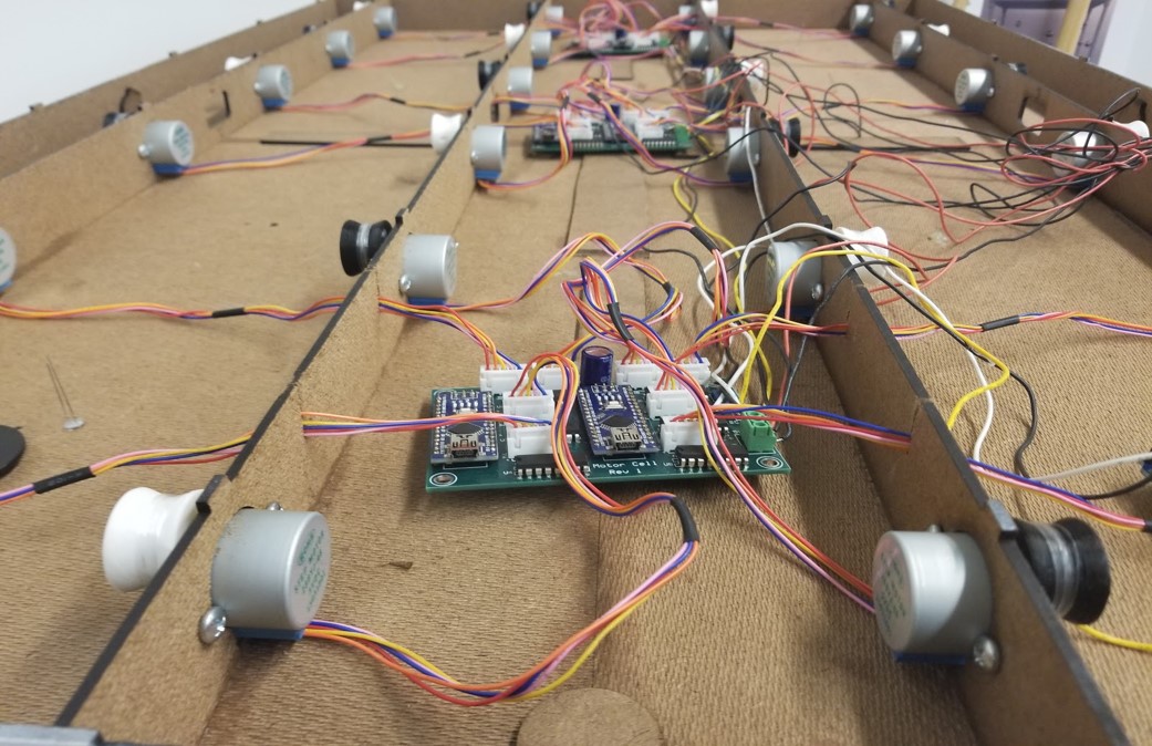
Printed Circuit Boards
Our decision to design printed circuit boards to control our kinetic cloud was a drastic but much-needed one. We had two problems, both of which stemmed from the number of stepper motors we were attempting to control. The first issue was power. With so many stepper motors, our estimated current draw was quite high. While we could supply this power through copper wire, we would need to make sure that the wire was the right gauge. While by itself it was not an impossible task, it fed into our second problem, wire management, and general circuit assembly.
Each stepper motor required five wires, one for power and four for controlling the stepper motor. With 24 motors this would mean there would be 120 wires just to connect to the motors, never mind all the other connections that would have to be made between slave Arduino Nanos. While designing PCBs would prove its own challenges, it would eliminate these two very daunting problems. Our team member Nathaniel had prior knowledge of PCB design and designed the PCBs.
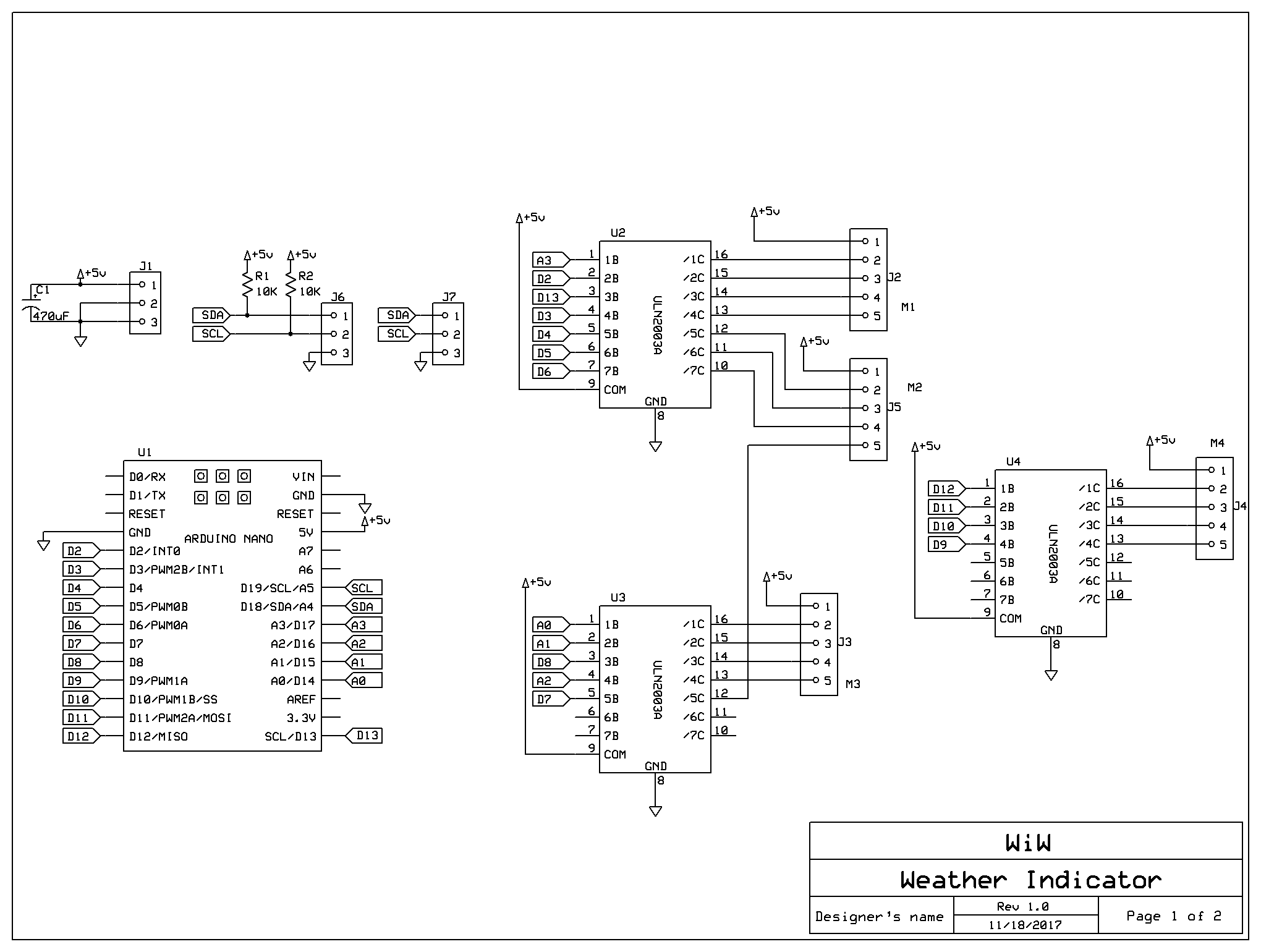
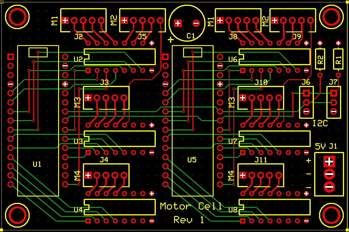
As previously stated, each board had two slave modules. Each slave module controlled four motors through the use of three ULN2003 Transistor Arrays. The ULN2003 IC has seven pins in and seven pins out while each stepper motor needs to be connected to three pins. Each slave module had one ULN2003 which controlled one stepper motor each while two of the ICs controlled three motors between them. Every board is powered by one 5V wire and two ground wires. It is very important that the reference voltage is constant across all components in the circuit. Due to the high current, a voltage drop on the power wires is a large possibility which is why there are two ground wires. A relatively large capacitor was put between power and ground for every board to help diminish the effect of any current spikes the board might experience.
The information given in this section has been an overview of all the different considerations we were taking into account when designing our electrical systems. If you would like more detail on our components and the actual assembly, please contact us using the information on our About Us page.