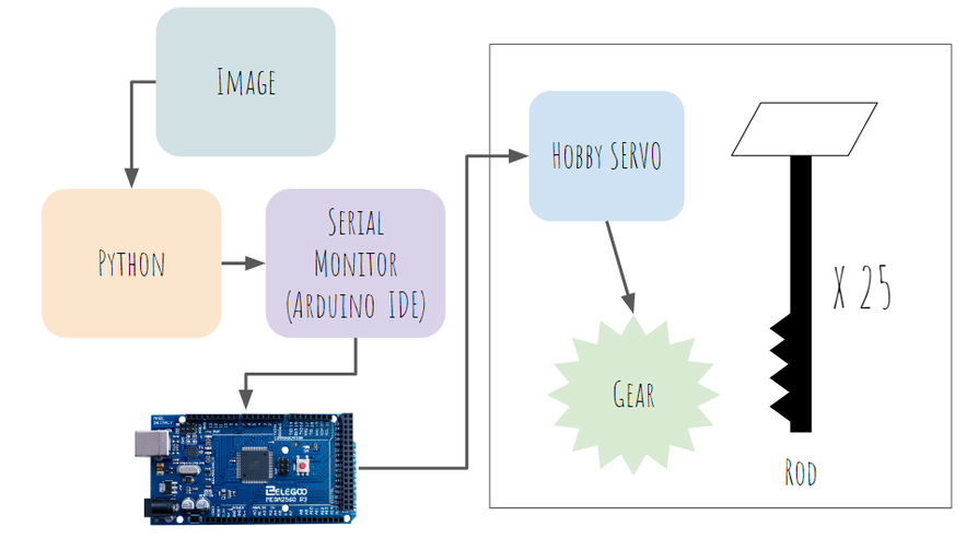
System Diagram
Mechanical Design
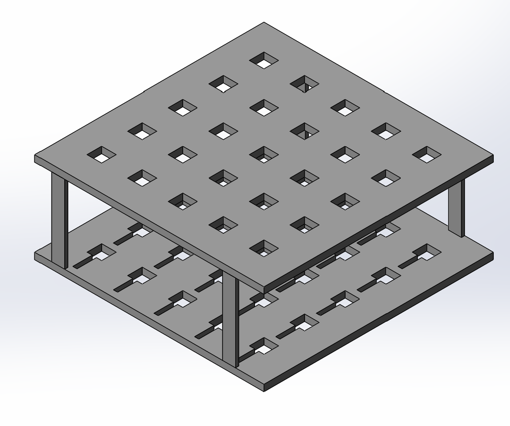 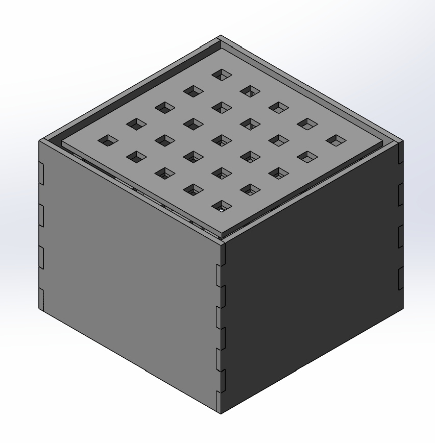 |
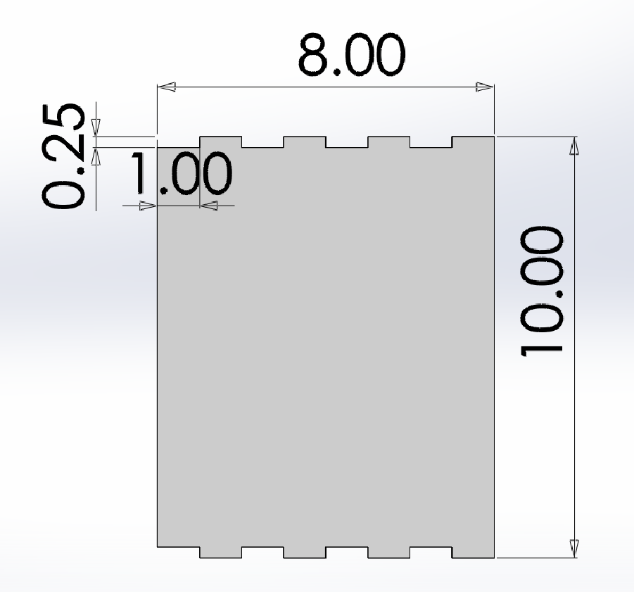
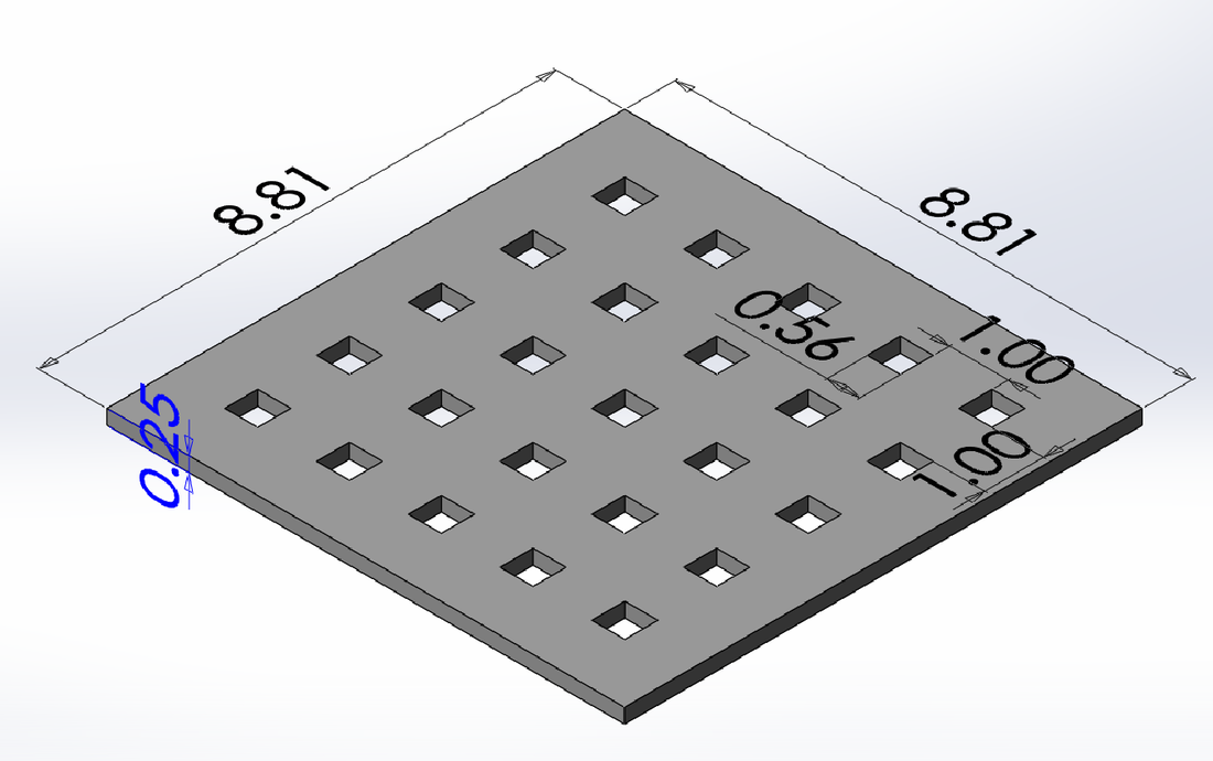
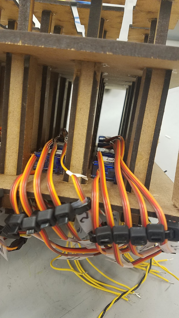
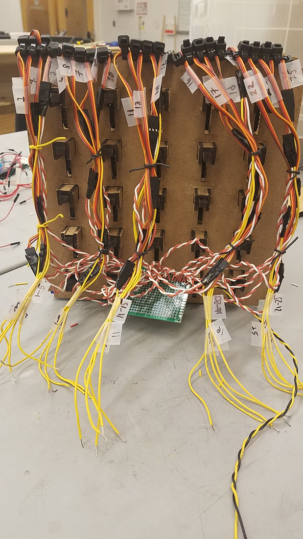
Mechapin's base design is made with 1/8" laser-cut MDF. There is a top plate above a bottom supporting plate, separated by spacers, and resting on four wooden legs. 25 servos are mounted to the middle plate, each attached to a laser cut 1/8" MDF gear which moves a 1/8" MDF pin. Between the top and bottom plates are supports for the pins. Squares are attached to the the tops of each pin, painted white for increased visibility. The entire assembly is covered with a painted four-sided MDF 1/4" press-fit box.
|
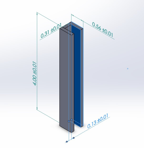
Support for pin (inches)
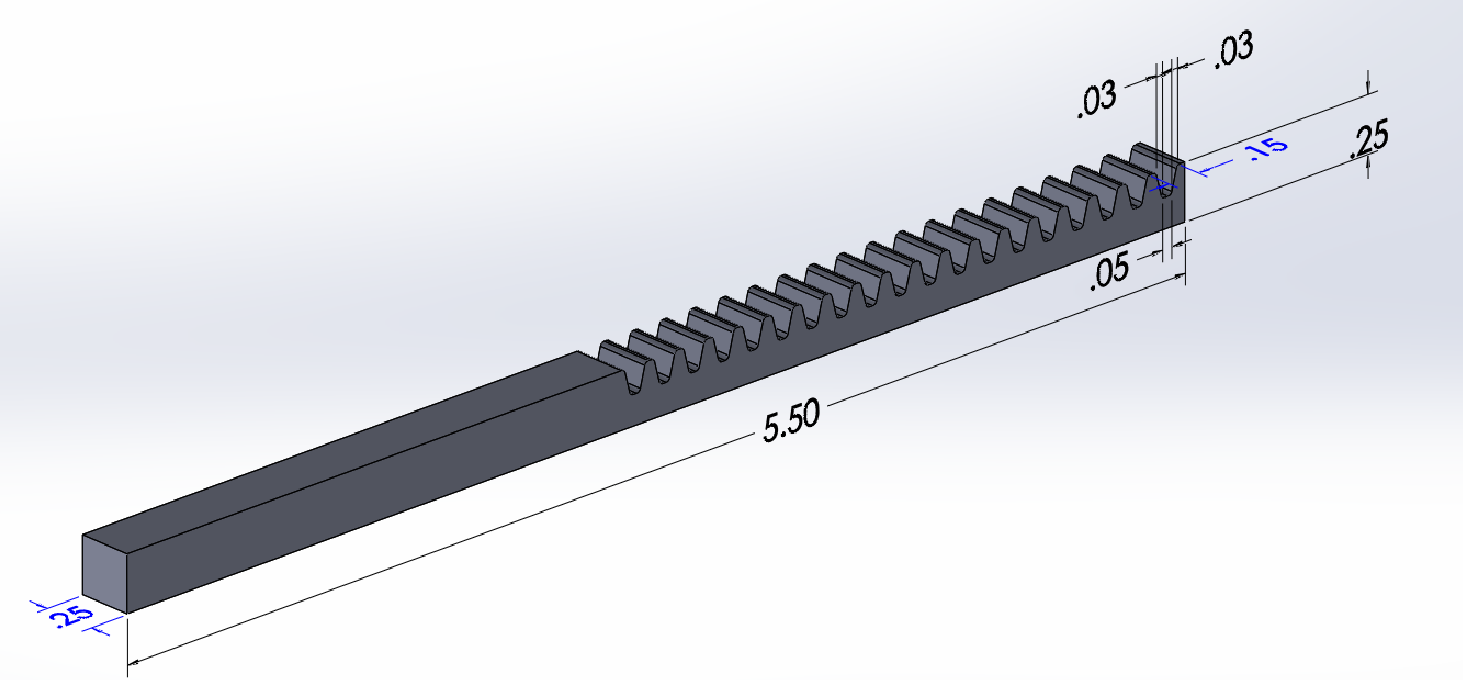
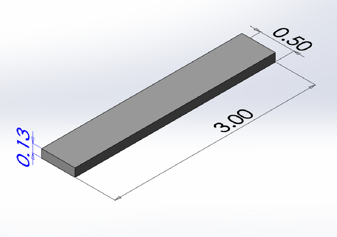
Pin (inches)
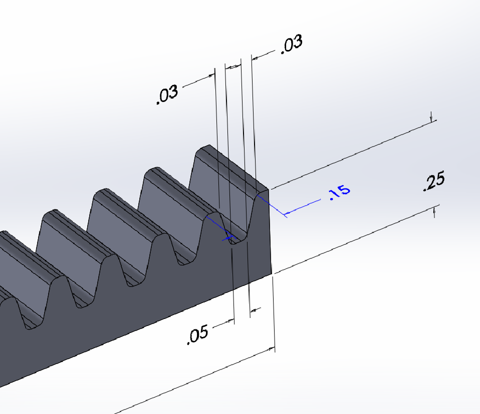
Close-up of pin (inches)
|
Box side (inches)
Top plate (inches)
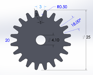
Gear (mm)
|
Support between plates (inches)
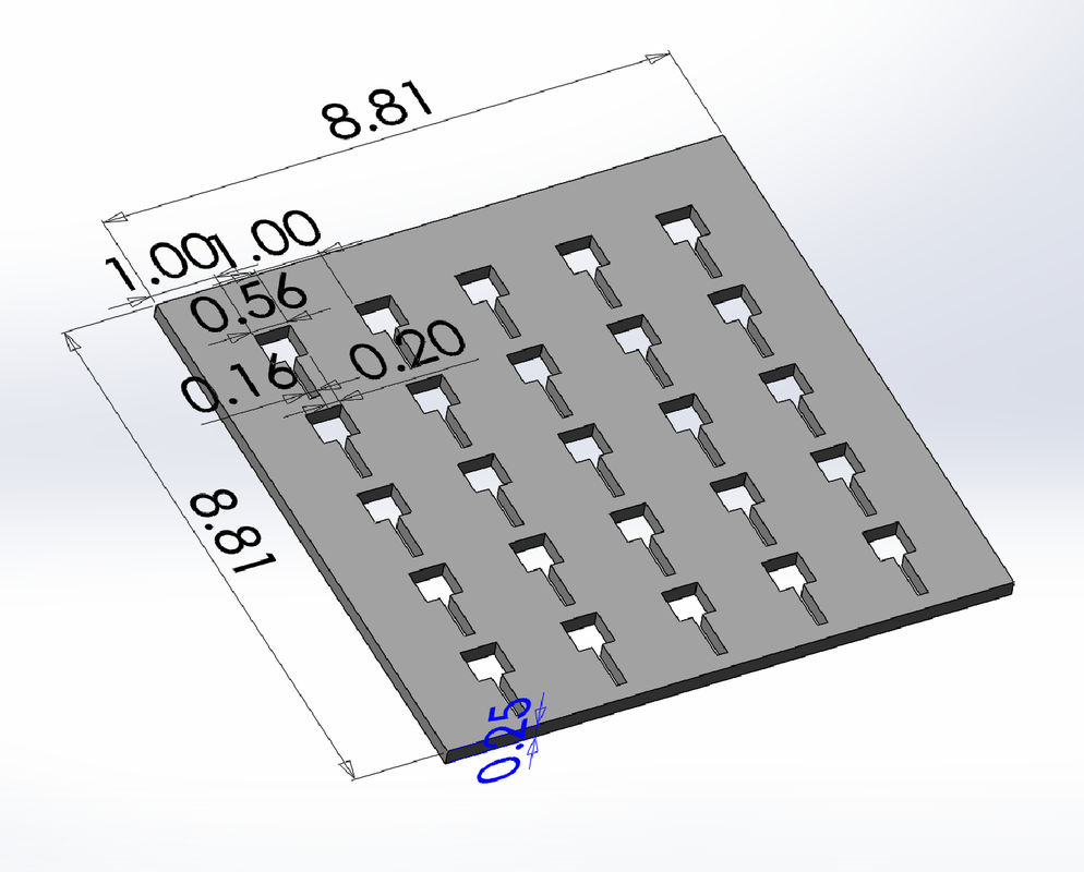
Bottom plate (inches)
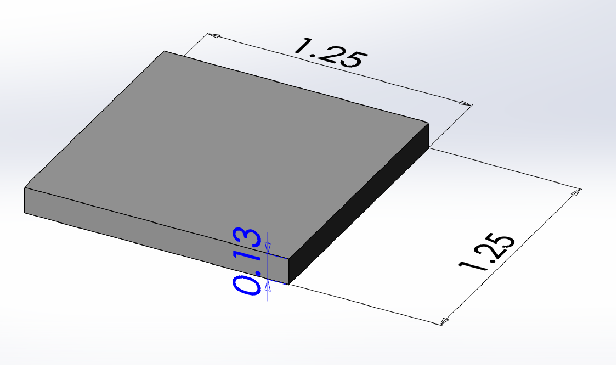
Top square (inches)
|
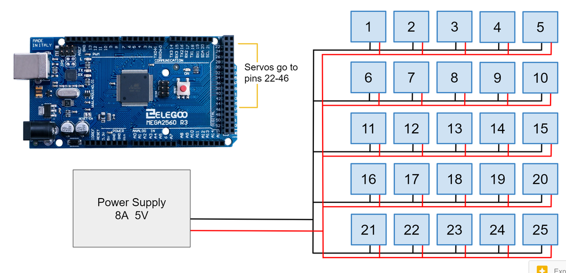
Electrical Design
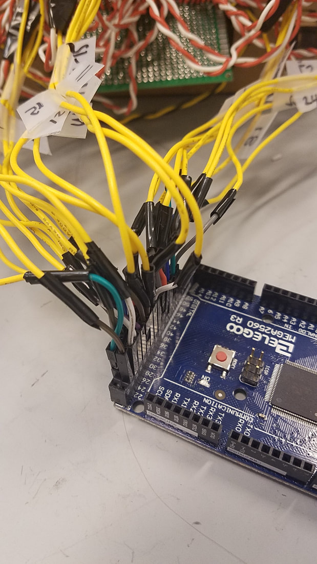
The 25 servos are all connected to a protoboard with power and ground lines, as well as to a Arduino Mega. The 25 servos are connected to pins 22 through 46 on the Mega. The array is powered by an adjustable power supply set to 5V and 8A and the ground is connected to the ground pin on the Mega as well.
Firmware/Software Design
The finalized code is here on Github.
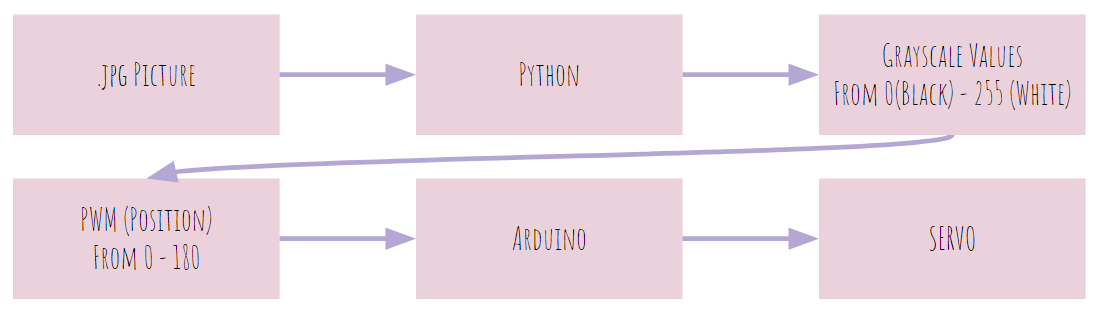
The diagram below shows how our software works. First, our python code takes simple square .jpg image. The image must be in the same folder where the python code is placed at. Then, python code pixelates the image, and convert the pixelated image into grayscale. Then, it obtains the grayscale values of each chunk of the pixels in the form of list. After then, our Arduino (we had to use Arduino Mega since they are the only Arduinos that supports more than 12 digital I/O) receives the grayscale values of the each pixel and moves the SERVO based on the value (Grayscale values are mapped out from 0 to 255 to 0 to 180 since PWM scale is different than grayscale).
The diagram below shows how our software works. First, our python code takes simple square .jpg image. The image must be in the same folder where the python code is placed at. Then, python code pixelates the image, and convert the pixelated image into grayscale. Then, it obtains the grayscale values of each chunk of the pixels in the form of list. After then, our Arduino (we had to use Arduino Mega since they are the only Arduinos that supports more than 12 digital I/O) receives the grayscale values of the each pixel and moves the SERVO based on the value (Grayscale values are mapped out from 0 to 255 to 0 to 180 since PWM scale is different than grayscale).
Next, we will walkthrough how we programmed the Mechapin. The code that we had for Sprint 2 and 3 are colored as gray and the final code is colored normally with explanations in red. Again, if you want walk-through for gray codes, you can check out our Sprint 2 python code walkthrough in the blog.
<Python code>
import sys
import matplotlib.pyplot as plt
import numpy as np
import PIL.Image as Image
import scipy.misc as misc
import csv
import serial
import time
import struct
grayvalues = []
def load_img(filename):
# boilerplate code to open an image and make it editable
# opens the file and convert it into grayscale by using PIL mode
img = Image.open(filename)
data = np.array(img)
# convert a grayscale image into array of data
return data
def all_square_pixels(row, col, square_h, square_w):
# Every pixel for a single "square" (superpixel)
# Note that different squares might have different dimensions in order to
# not have extra pixels at the edge not in a square. Hence: int(round())
for y in range(int(round(row*square_h)), int(round((row+1)*square_h))):
# renders through row values
for x in range(int(round(col*square_w)), int(round((col+1)*square_w))):
# renders through column values
yield y, x
# yield reads only once, number of pixels in original image
def make_one_square(img, row, col, square_h, square_w):
# Sets all the pixels in img for the square given by (row, col) to that
# square's average color
pixels = []
# get all pixels
for y, x in all_square_pixels(row, col, square_h, square_w):
pixels.append(img[y][x])
# get the average color
av_r = 0
av_g = 0
av_b = 0
for r, g, b in pixels:
# add rgb values as it goes through for loop
av_r += r
av_g += g
av_b += b
av_r /= len(pixels)
av_g /= len(pixels)
av_b /= len(pixels)
# set all pixels to that average color
for y, x in all_square_pixels(row, col, square_h, square_w):
img[y][x] = (av_r, av_g, av_b)
# print(av_r, av_g, av_b)
avg_Gray = int(round(0.2989 * av_r + 0.5879 * av_g + 0.1140 * av_b))
# print(avg_Gray)
grayvalues.append(avg_Gray)
def rgb2gray(rgb):
# converts rgb value into grayscale
# grabs the rgb data from an image and converts it into intensity
# Y' = 0.2989r + 0.5879g + 0.1140b is used for formula
r, g, b = rgb[:, :, 0], rgb[:, :, 1], rgb[:, :, 2]
gray = 0.2989 * r + 0.5879 * g + 0.1140 * b
return gray
if __name__ == "__main__":
try:
filename = sys.argv[1]
# save user's input on cmd line as filename
except IndexError:
filename = input("Choose an image to pixelate ")
# if there's no input with keyboard, ask what image to pixelate
img = load_img(filename)
# load the iamge
# Figure out the dimensions of each square
num_cols = 5
# width of the square
square_w = float(img.shape[1]) / num_cols
# determine the row number based on the width of the square
num_rows = int(round(img.shape[0] / square_w))
# height of the square
square_h = float(img.shape[0]) / num_rows
# overwrite each square with the average color, one by one
# basically, part of an image is colored as average color
# call function for entire image
for row in range(num_rows):
for col in range(num_cols):
make_one_square(img, row, col, square_h, square_w)
csvfile = "/home/minju/Bao_POE/Grayscalve_Vals.csv"
foo = open(csvfile, 'w')
foo.truncate()
foo.close()
with open(csvfile, 'a') as output:
writer = csv.writer(output, lineterminator='\n')
writer.writerows([[vals] for vals in grayvalues])
At first, we tried to establish the serial connection between the arduino and python by dumping grayscale values as .csv file from python and making arduino to read the values from .csv file. After a while, we realized that we can establish a connection directly from python to arduino using pyserial. The sculpture works without the codes above. It just dumps the grayscale values as .csv. If you still want to have the codes above, you should have a blank file before you run the code for the first time. Then, define the file directory.
# convert the image into gray scale
# if you want to use rgb image, just comment this line out
gray = rgb2gray(img)
# show the image
plt.axis('off')
plt.imshow(gray, cmap='gray')
plt.show()
# save the image as filename_pixelated
filename_parts = filename.rsplit('.', 1)
filename_parts[0] += '_pixelated'
filename = '.'.join(filename_parts)
print("Saving Pixelated Image")
misc.imsave(filename, gray)
port = '/dev/ttyACM0'
ser = serial.Serial(port, 9600)
Connects Arduino’s serial monitor and python. Arduino’s port can be checked at the right bottom part of Arduino IDE. In linux, the port is in the form of ‘/dev/tty….’ and in Windows, it is in the form of ‘COM10’. .Serial takes the port address and baud rate. Since our baud rate is 9600 in our arduino, it would be .Serial(port, 9600).
for i in grayvalues:
ser.write(chr(i).encode("latin1"))
print("Sending Values:")
print(i)
time.sleep(1.5)
Then, send grayscale values one by one to Arduino’s Serial monitor. It sends the value once in 1.5 seconds. Before it sends the grayscale value, the values(binary) should be converted into hexadecimal string since .write only takes hex. Therefore, you have to convert the grayscale value to string hexadecimal by using chr().encode(“latin1”) before you send it to Arduino’s serial monitor. Any values that are under 1.5 does not work since Arduino’s serial monitor needs to settle down after opens up the connection.
<Arduino Codes>
#include <Servo.h>
const byte servoCount = 25;
Servo servo[servoCount];
Creates 25 servo objects all at once. This can be done by indexing servos as an array.
const int initpos = 0;
Define the initial position of the servo when the code runs.
void setup(){
Serial.begin(9600);
Serial.println("Ready to go!");
Begins the serial monitor and print out “Ready to go!” to see if serial monitor is ready to accept the values from python.
// attach servos
servo[1].attach(22);
servo[2].attach(23);
servo[3].attach(24);
servo[4].attach(25);
servo[5].attach(26);
servo[6].attach(27);
servo[7].attach(28);
servo[8].attach(29);
servo[9].attach(30);
servo[10].attach(31);
servo[11].attach(32);
servo[12].attach(33);
servo[13].attach(34);
servo[14].attach(35);
servo[15].attach(36);
servo[16].attach(37);
servo[17].attach(38);
servo[18].attach(39);
servo[19].attach(40);
servo[20].attach(41);
servo[21].attach(42);
servo[22].attach(43);
servo[23].attach(44);
servo[24].attach(45);
servo[25].attach(46);
Attach the 25 SERVOS to corresponding digital I/O pins at MEGA2560. Again, indexing is used. Index can start from 0, but for the sake of convenience, we started the index from 1.
}
void loop(){
byte index = 1;
Define the class type of index and initialize it by setting it to 1.
for (byte servoindex = 1; servoindex < servoCount; servoindex++)
{
servo[servoindex].write(initpos);
}
Move 25 SERVOS to initpos, which is 0. Whenever you run the code, initialize the sculpture by moving them to position 0.
while(true)
{
While loop enables arduino to listen to python all the time without terminating established connection between python and arduino.
if(Serial.available() > 0)
{
digitalWrite(13, !digitalRead(13));
Make built-in LED of arduino to blink whenever arduino receives a value. This line is included for the diagnosis purpose.
byte serv_pos = Serial.read();
Fetch the incoming serial value and save it as serv_pos.
serv_pos = map(serv_pos, 0, 255, 0, 180);
Maps out grayscale value (0 to 255) to PWM value (0 to 180).
Serial.print(serv_pos);
Serial.print(", ");
Serial.println(index);
Print out the values for diagnosis.
servo[index].write(serv_pos);
index = index + 1;
Moves the servo to its position and increment the index value by one whenever there is a new value incoming through serial monitor. In that way, we could control multiple servos one by one. For example, first servo moves to whatever value it fetched from serial monitor for the first time. Then, when arduino detects second value came through serial monitor, second servo moves correspondingly. Third arduino moves when third grayscale value incomes and so on. The term between each servos is 1.5 seconds (In other word, one servo moves in 1.5 seconds. This means, the entire image would be displayed in 37.5 seconds).
}
}
}
Wow, we actually did it. It seems like there are not so much codes added after sprint 2. However, our final code is the result of countless debugging process. We also get to learn a lot about how data transmission works. For example, we learned why maximum grayscale value is 255, not 100 and why arduino only takes hexadecimal. We learned so much from overcoming our software technical challenges.