Final Reflection - Hanna
12/13/17
Written by Hanna
Working on the Mechapin project, I felt that I gained a lot of knowledge of techniques and fabrication methods. Although my goals for this project were to improve in both fabrication and CAD, I unfortunately was unable to further develop my experience with CADing softwares as it was difficult for me to find a computer that had a CAD software on it. I was however, able to further my knowledge of fabrication, from learning how to use (and somewhat fix) the two 3D printers available at Olin, to learning how to use the Helix laser cutter available. In general, I am very happy with how our project turned out, we were able to achieve our MVP. Although we were unable to implement all of the ideas that we wanted, such as preloaded images that a user could press a button to rotate through, we are still very happy with our end result.
Final Reflection - Minju
12/13/17
Written by Minju
During the final project, I really learned a lot and also felt very proud of myself when the project ended. Before Principles of Engineering, I really didn’t have confidence in my coding ability. It really was my first time coding for Arduino and I got nervous when I realized that some of our teammates don’t know how to code at all. I felt a lot of responsibility on my shoulder and I didn’t want to do it, but I wanted to not disappoint my teammates. I started with some googling. There were many examples that covers very basic functionalities of our codes. Then, I realized I really should start with tutorials for python libraries and look at documentation instead of directly diving into stack exchange. After that, I started to write entire code by myself. It was soemtimes catastrophic. There were countless error messages. Sometimes, the program didn’t return any messages but behave in unexpected way. One time, I had to sat down in POE room for 4 hours just to debug two lines of error message. After all pains, I made it. With help of Sarah, NINJAs, and faculties help, I managed myself to write robust code. I’m really proud of it. I learned how to overcome my fear of blank space in IDE, how to properly look at documentation, how to google, how to ask help, and finally, how to communicate with my team. Without my team’s support, I would never be able to achieve what I’ve done.
Final Reflection - Sarah
12/12/17
Written by Sarah
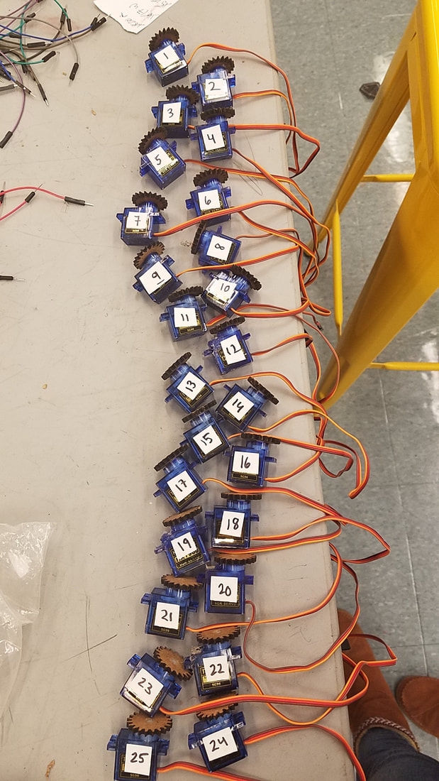
I'm so happy our team accomplished our MVP and our finals demos went smoothly. During this project, I've personally learned quite a lot of skills, the main one being CAD. Before PoE, I knew how to CAD simple designs like boxes, but after some frustrating hours and many YouTube tutorials later, I know how to make gears and racks, how to repeat linear and circular patterns, and I got much better at mating parts together in assemblies. I spent a lot of time on PoE this semester since I had a lighter course load, but I'm glad I was able to contribute to our project, whether it was tedious tasks like re-wiring 25 servos many many times or filing laser-cut pieces for an hour when they didn't fit, or learning new skills, like soldering on protoboards, using a bench-top power supply, writing Arduino test code, or CADing. I finally got trained on the laser cutter at Olin, and while I had trouble getting the laser-cutter to connect to my laptop, I got a lot of experience laser-cutting with Kai. I wish I had helped Minju out more with the Python code, but I got rid of my Linux partition after SoftDes last spring and am slowly figuring out coding Python in Windows. Overall, I had a really fun time this semester with Team BAO, and while we may not have had the most intricate project out of the PoE teams, I think we all learned a lot and had fun creating a cool art piece!
Written by Sarah
I'm so happy our team accomplished our MVP and our finals demos went smoothly. During this project, I've personally learned quite a lot of skills, the main one being CAD. Before PoE, I knew how to CAD simple designs like boxes, but after some frustrating hours and many YouTube tutorials later, I know how to make gears and racks, how to repeat linear and circular patterns, and I got much better at mating parts together in assemblies. I spent a lot of time on PoE this semester since I had a lighter course load, but I'm glad I was able to contribute to our project, whether it was tedious tasks like re-wiring 25 servos many many times or filing laser-cut pieces for an hour when they didn't fit, or learning new skills, like soldering on protoboards, using a bench-top power supply, writing Arduino test code, or CADing. I finally got trained on the laser cutter at Olin, and while I had trouble getting the laser-cutter to connect to my laptop, I got a lot of experience laser-cutting with Kai. I wish I had helped Minju out more with the Python code, but I got rid of my Linux partition after SoftDes last spring and am slowly figuring out coding Python in Windows. Overall, I had a really fun time this semester with Team BAO, and while we may not have had the most intricate project out of the PoE teams, I think we all learned a lot and had fun creating a cool art piece!
Final Reflection - Kai
12/11/17
Written by Kai
This semester, we set out to create an art piece, and I feel that we accomplished our goal. In terms of my own personal goals, I wanted to gain general engineering experience and fabrication experience. I feel I achieved the latter goal most of all. The machining for our final construction was almost exclusively laser cutting, much of which I did. I also did a fair amount of gluing to assemble the final construction. In terms of my “general engineering experience” goal, I also did a little CAD and, earlier on in the semester, helped set up the mini-servos. In hindsight, I wish I could have done more with the Arduino IDE, but I’m happy with my learning. I think it would have been nice to be able to incorporate a button and more images in our final product, but we reached all points of our MVP, so I’m happy with that.
Getting Ready for Demo Day Pt. 2
12/11/17
Written by Kai
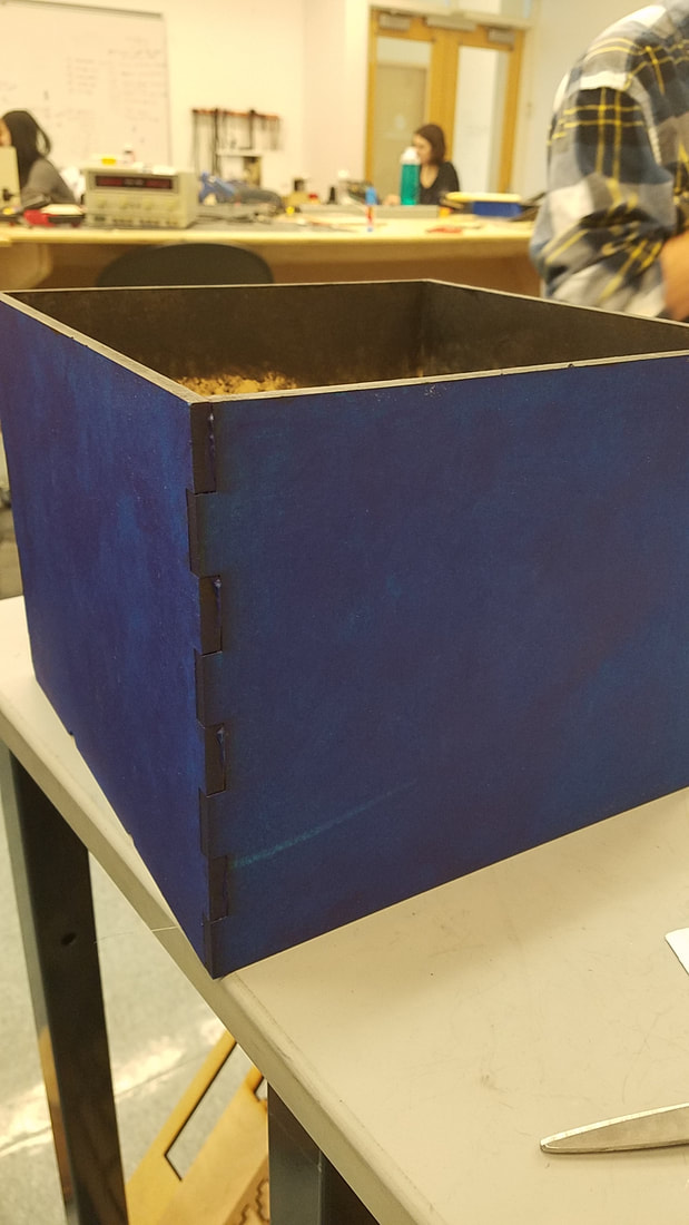
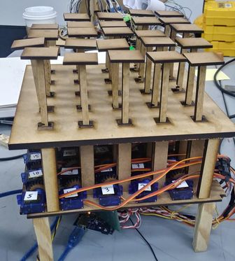
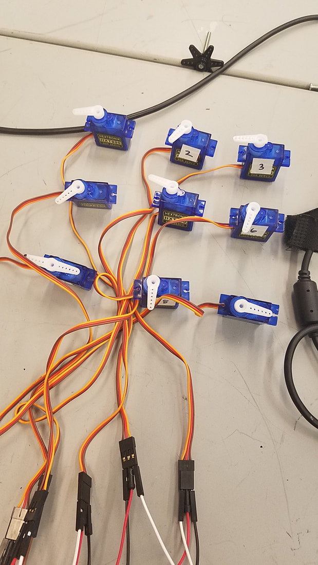
We’re on to our last sprint before demo day, so this is our last opportunity to clean up our system and make it look as aesthetic as possible. We have organized our wiring with zip ties and numbered labels, and replaced our original breadboard with a soldered protoboard to make the system more robust. We cut a press-fit box out of wood to cover up our wires and boards, with a hole for wires to go through. Minju fixed some bugs in the code, namely indexing and timing issues with the servos.
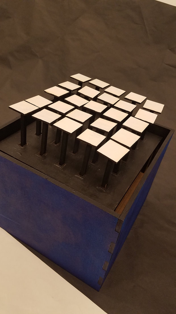
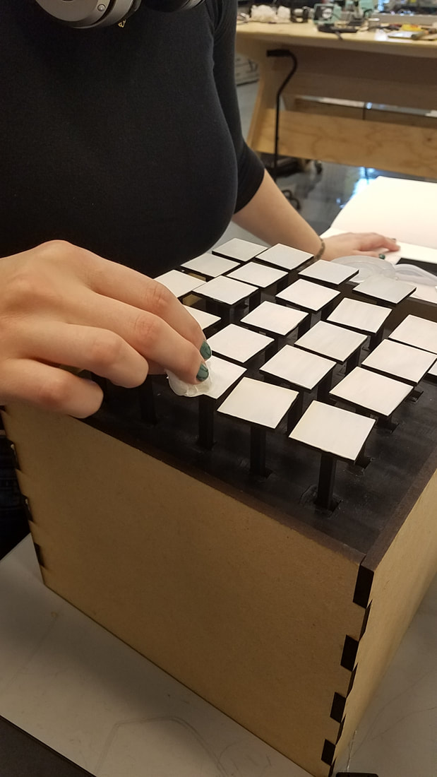
We have painted the entire construction black, save for the tops of the pin squares which are white. This maximizes contrast between the tops of the squares and everything else, making the images easier to see. We also painted our box blue to make the structure more aesthetically pleasing.
Another tweak we’ve made to improve the system’s appearance is increasing the length of the supporting legs to give the array slightly more height and to allow more room for the wires and arduino (Elegoo) knock-off.
Written by Kai
We’re on to our last sprint before demo day, so this is our last opportunity to clean up our system and make it look as aesthetic as possible. We have organized our wiring with zip ties and numbered labels, and replaced our original breadboard with a soldered protoboard to make the system more robust. We cut a press-fit box out of wood to cover up our wires and boards, with a hole for wires to go through. Minju fixed some bugs in the code, namely indexing and timing issues with the servos.
We have painted the entire construction black, save for the tops of the pin squares which are white. This maximizes contrast between the tops of the squares and everything else, making the images easier to see. We also painted our box blue to make the structure more aesthetically pleasing.
Another tweak we’ve made to improve the system’s appearance is increasing the length of the supporting legs to give the array slightly more height and to allow more room for the wires and arduino (Elegoo) knock-off.
Getting ready for Demo Day Pt. 1
12/8/17
Written by Miguel
Getting ready for Demo Day, Team BAO still had some last minute fixes and improvements to take care of. First off, we wanted to take care of the small bugs in the system that would make our project work more precisely. After assembling our sculpture, we noticed that our pins are different heights. In order for everything to be level and better show off the display, the pins needed to be calibrated to the same height.
Next, our team wanted to focus in on the aesthetic aspects of our design. Having an art piece, we wanted to improve on the artistic side of the project. There are several modifications that can enhance our structure's experience, such as painting our base structure black, painting our squares white, and adding a hole in our box for wires.
|
|
Sprint 3 - Reflection
12/4/2017
Written by Kai
In Sprint 3, we worked to complete our MVP and for the most part we accomplished it! We constructed our 5 x 5 array and it was slightly operational. We did all of our design and some of the laser cutting before Thanksgiving break, but lost some of our momentum after break. We ran into some similar problems as last sprint, i.e. assembling a little too last-minute to make the construction super polished (the visualized image is not super clear. The servos aren’t completely aligned in the initial position. Also, the squares on top of the pins are cardboard at the moment). We also need to debug serial communication between Python and Arduino, which Minju has been working on and making great progress with. Overall, we have our 5 x 5 array more or less connected, assembled, and working, so we will hopefully have time to clean it up before demo day.
Before demo day, we want to make sure the array is fully operational and polished. We’ll decide how we want the pins to look, make sure the pins are aligned, and decide on any additional features we want to add. We will also construct a box or fabric cover to hide the wires, servos, and board. There were also some suggestions from the class for making the system more aesthetic (mainly covering up wires, which we already plan to address before demo day, and also things like adding color or fabric).
We’ll also need to decide what we want the user experience to be, and how to demo our project. We have several options to discuss and decide on (e.g. controlling the array with a button, through a computer, or some combination of both). We asked for class feedback on preferred user experience and many people said they’d want a button, and some people said they’d also want to be able to touch the array.
Sprint 3 - Assembly and Testing
11/27/2017
Written by Sarah
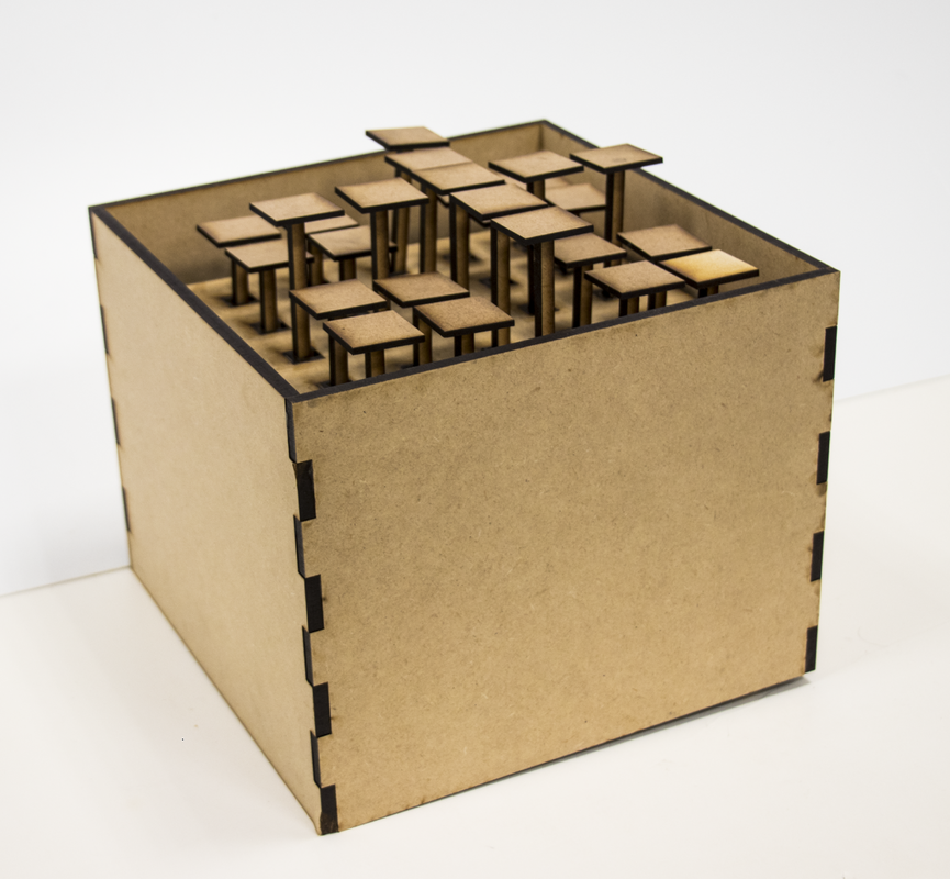
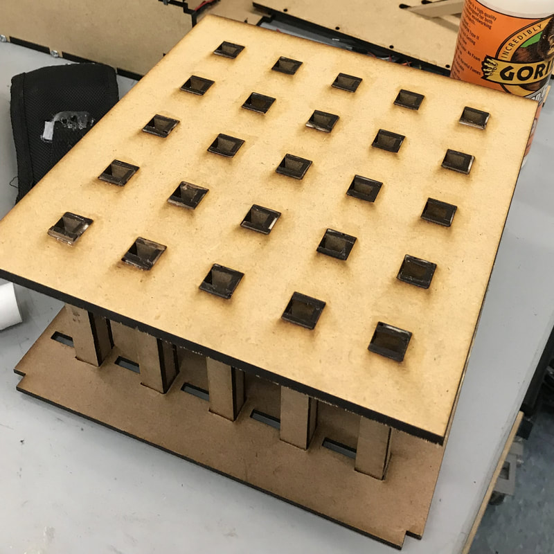
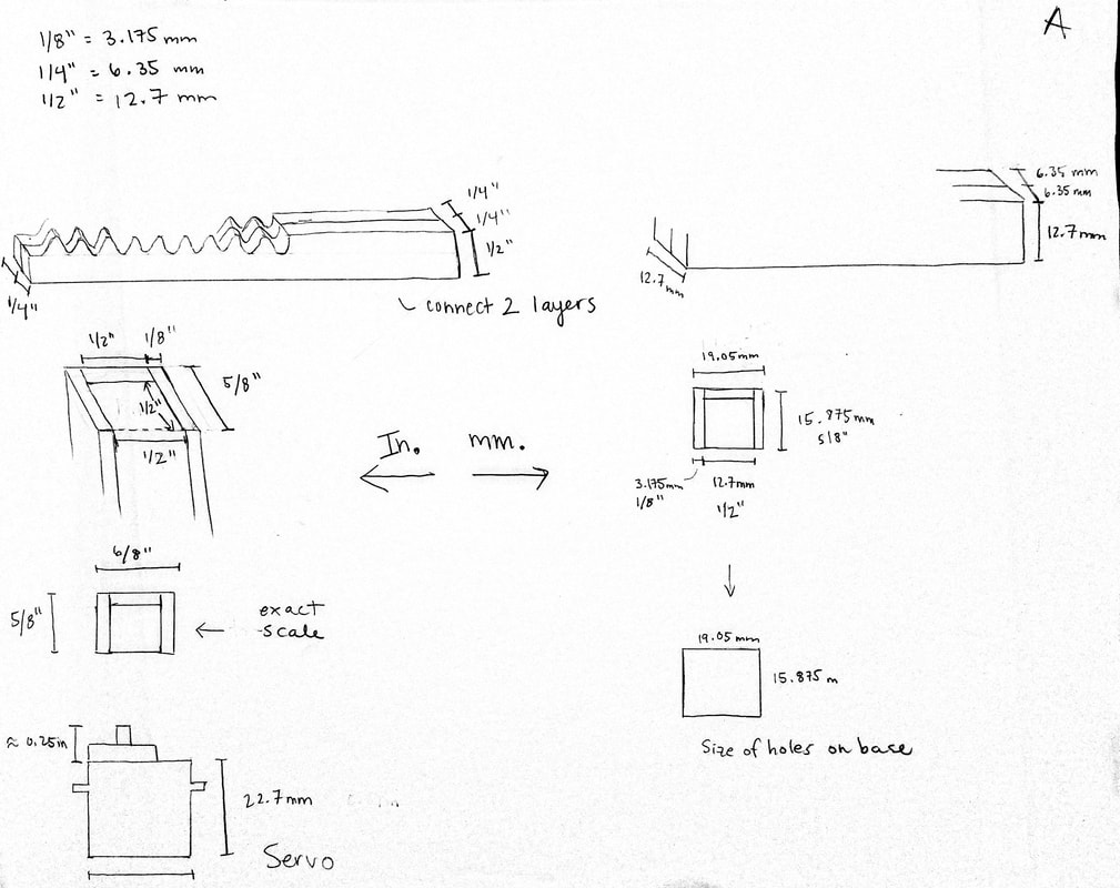
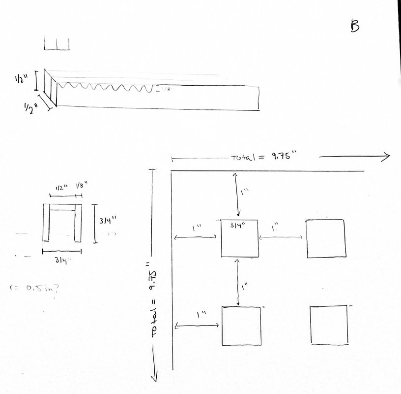
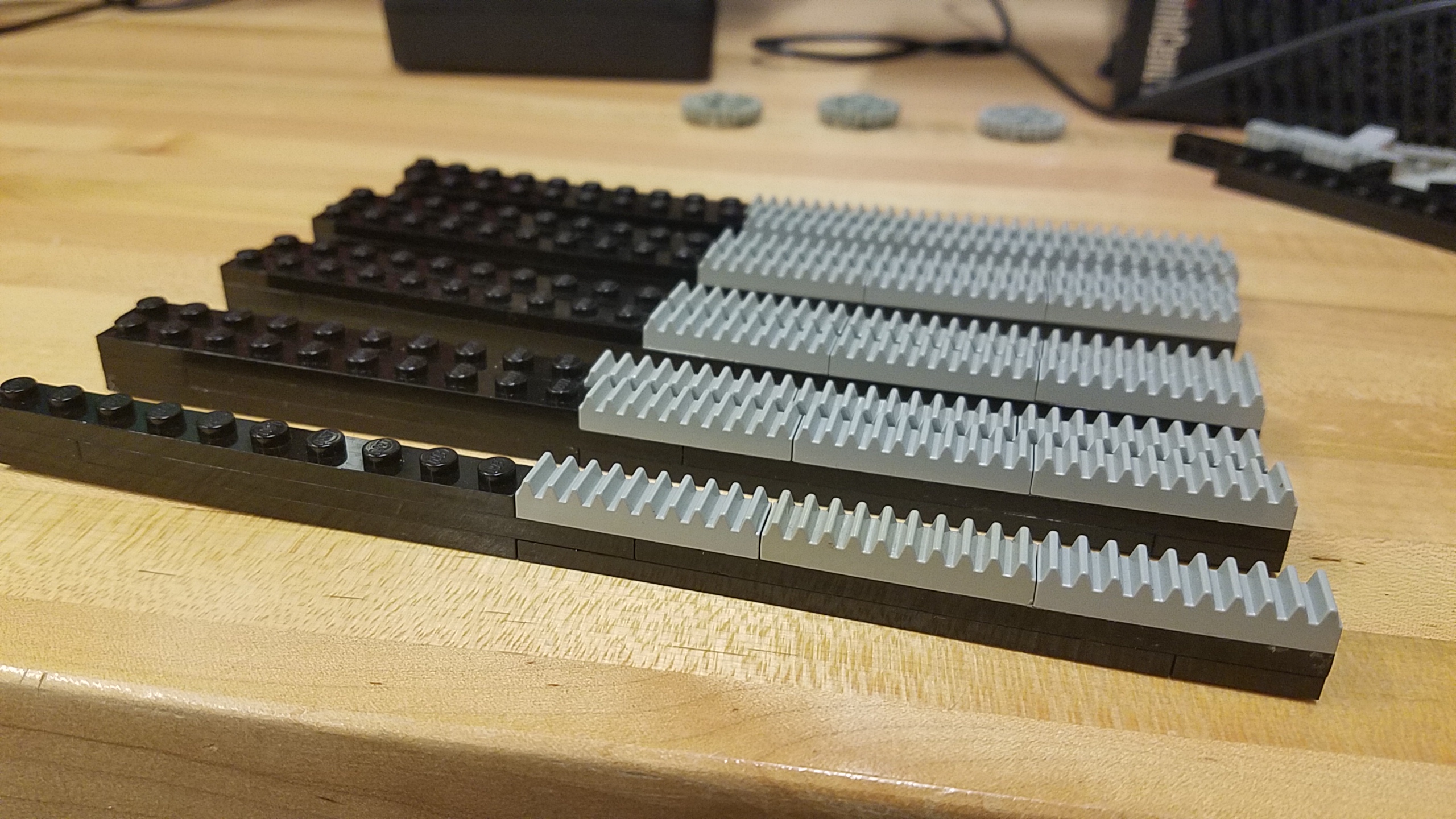
We began laser cutting our parts and testing out different sizes for pins, supports, and gears. We cut and glued some parts before Thanksgiving and cut the rest when we returned from break. In this new design, we’ve made the pins a lot smaller, since they don’t need to be large. This is saving a lot of material and time.
We also cut our two plates and all of the supports and began assembling them. We found that gluing the supports introduces a lot of impreciseness, so fitting them into the plates has been difficult. In future, we may make our supports use press fits or some other joining mechanism instead of gluing.
Written by Sarah
We began laser cutting our parts and testing out different sizes for pins, supports, and gears. We cut and glued some parts before Thanksgiving and cut the rest when we returned from break. In this new design, we’ve made the pins a lot smaller, since they don’t need to be large. This is saving a lot of material and time.
We also cut our two plates and all of the supports and began assembling them. We found that gluing the supports introduces a lot of impreciseness, so fitting them into the plates has been difficult. In future, we may make our supports use press fits or some other joining mechanism instead of gluing.
Sprint 3 - Redesigning the Base
11/16/2017
Written by Sarah
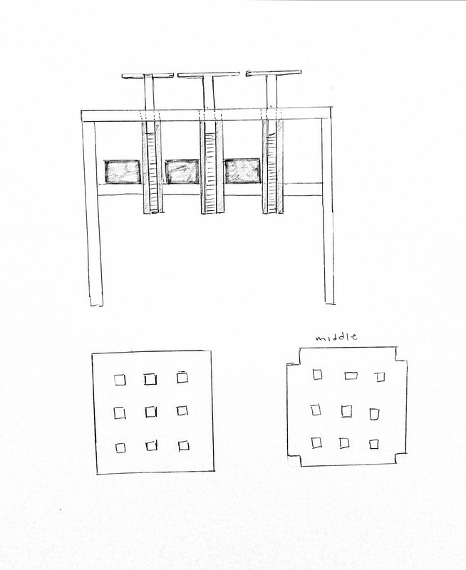
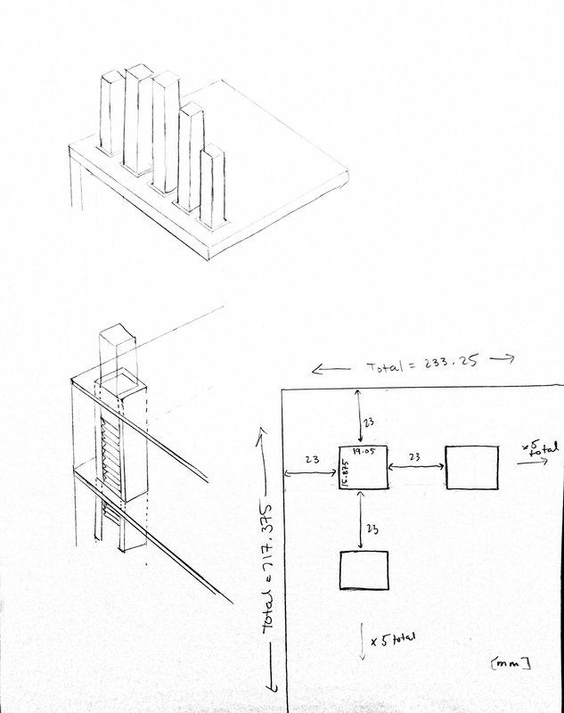
After Sprint 2, we did some major brainstorming and sketching on the design and dimensions of our structure. We are expanding from a 3 x 3 array of pins to a 5 x 5 array of pins, so we have to re-CAD the parts to accommodate more servos and pins.
Here are some sketches that we did when we were working on dimensions. We wanted to minimize the space between pins, so we made the spacing only just large enough to fit the servos. We also decided to make a middle plate so that the servos could sit on top of it and it will also give the supports more stability. These likely aren’t the final dimensions because we are going to cut some test pieces and iterate on the pin, rack, and gear designs.
Written by Sarah
After Sprint 2, we did some major brainstorming and sketching on the design and dimensions of our structure. We are expanding from a 3 x 3 array of pins to a 5 x 5 array of pins, so we have to re-CAD the parts to accommodate more servos and pins.
Here are some sketches that we did when we were working on dimensions. We wanted to minimize the space between pins, so we made the spacing only just large enough to fit the servos. We also decided to make a middle plate so that the servos could sit on top of it and it will also give the supports more stability. These likely aren’t the final dimensions because we are going to cut some test pieces and iterate on the pin, rack, and gear designs.
Sprint 2 - Reflection
11/15/2017
Written by Kai
For Sprint 2, we completed our 3x3 array and image processing, though the physical construction was not particularly robust, and only two of our pins were 3D printed; the remaining seven were made of Legos as in Sprint 1.
Much of our peer feedback was about the rough appearance of the system and limited image resolution it could provide, both of which are aspects that the team is working hard to improve this upcoming sprint.
Most of our trouble in Sprint 2 arose from prototyping too slowly. Our final array was constructed last-minute, and the pins took far too long to 3D print too, so we couldn’t have more than two prepared for the sprint review. Also, our servos weren’t mounted properly and so the pins often became misaligned and fell off. As a result, the system looked unpolished and was not particularly sturdy.
We kept this in mind as we completed our Sprint 2 retrospective after the presentations last Friday. Most of our “plusses” had to do with good team health, especially teamwork and active communication. Our “deltas” had to do mostly with faster fabrication and iteration. In response to this, we decided that our new kaizen for Sprint 3 is to create a polished system, which will require rapid prototyping.
We have a tangible goal for sprint 3: a clean, robust, 5x5 system (we’re skipping 4x4 for the sake of efficiency), which will require us to work more quickly. Currently, Minju has been working on GUI tutorials to create a good interface for our system. Kai and Sarah have been working on prototyping laser cut pins, to get a head start on design a more robust system. We also plan to better integrate the Arduino and Python code.
To reach our goal, we’ve created rough mini-deadlines in Sprint 3. Shortly after the review, we placed orders for more mini-servos and an off-brand arduino-compatible mega board. We aim to have the platform and supports designed, laser cut, and assembled by this Friday, i.e. before Thanksgiving break. We’ve modified our platform design to be sturdier, and our pins will be laser cut rather than 3D printed, which will also allow us to prototype faster. We can begin mounting as many servos as we have, and once our orders come in, we can begin attaching the servos.
Sprint 2 - Python Code
11/13/2017
Written by Minju
In this post, we will go over how the python code for sprint 2 works. To run the script, you need following libraries:
First, import the libraries.
import sys
import matplotlib.pyplot as plt
import numpy as np
import PIL.Image as Image
import scipy.misc as misc
Then, define a function for loading an image. This function opens an image and converts the image into an array of data (n by n (n = number of pixel in width or height of an image); each element in the array represents the r,g,b values of corresponding pixel). Since our sculpture only supports a square image, the length and height of the array should be same. Afterall, return the array so that it can be used for other functions.
def load_img(filename):
# open an image and make it editable by converting image into an array
img = Image.open(filename)
data = np.array(img)
return data
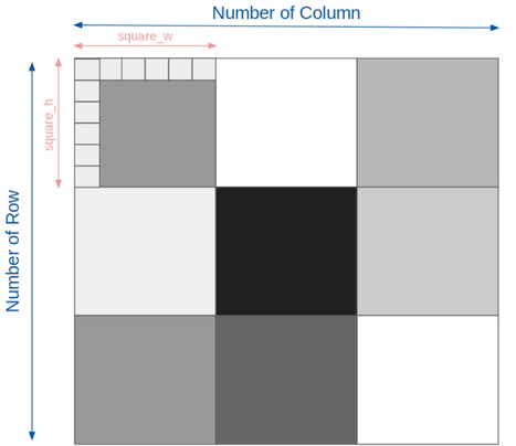
all_square_pixels function takes number of chunks of pixels for row and columns, and number of pixels for height and width of single “square (chunk of pixels)”. This function calculates the number of pixels for entire image. col and row are the number of chunks and square_h and square_w represents the number of pixels for height and width of a single chunk. Multiplying number of column and square_w would yield the number of pixel for entire image. Then, round the number to get the integer value. Depending on number of column, square_w or square_h can be decimals which we do not want for the sake of simplicity. Therefore, we rounded the variable and convert the data type to integer. Rounding (round()) a variable would still yield float value (e.g. 24.5 → 24.00) therefore we need to convert the variable's class to integer with int(). Same equation and logic are applied to row and square_h.Then, return the calculated x and y value, which will be used for make_one_square.
def all_square_pixels(row, col, square_h, square_w):
# Every pixel for a single "square" (superpixel)
# Note that different squares might have different dimensions in order to
# not have extra pixels at the edge not in a square. Hence: int(round())
for y in range(int(round(row*square_h)), int(round((row+1)*square_h))):
# renders through row values
for x in range(int(round(col*square_w)), int(round((col+1)*square_w))):
# renders through column values
yield y, x
# yield reads only once, number of pixels in original image
Written by Minju
In this post, we will go over how the python code for sprint 2 works. To run the script, you need following libraries:
- sys module (for saving processed images with different filename)
- Matplotlib (plotting image)
- Numpy (converting image into data array)
- PIL (image processing)
- Scipy (image processing)
First, import the libraries.
import sys
import matplotlib.pyplot as plt
import numpy as np
import PIL.Image as Image
import scipy.misc as misc
Then, define a function for loading an image. This function opens an image and converts the image into an array of data (n by n (n = number of pixel in width or height of an image); each element in the array represents the r,g,b values of corresponding pixel). Since our sculpture only supports a square image, the length and height of the array should be same. Afterall, return the array so that it can be used for other functions.
def load_img(filename):
# open an image and make it editable by converting image into an array
img = Image.open(filename)
data = np.array(img)
return data
all_square_pixels function takes number of chunks of pixels for row and columns, and number of pixels for height and width of single “square (chunk of pixels)”. This function calculates the number of pixels for entire image. col and row are the number of chunks and square_h and square_w represents the number of pixels for height and width of a single chunk. Multiplying number of column and square_w would yield the number of pixel for entire image. Then, round the number to get the integer value. Depending on number of column, square_w or square_h can be decimals which we do not want for the sake of simplicity. Therefore, we rounded the variable and convert the data type to integer. Rounding (round()) a variable would still yield float value (e.g. 24.5 → 24.00) therefore we need to convert the variable's class to integer with int(). Same equation and logic are applied to row and square_h.Then, return the calculated x and y value, which will be used for make_one_square.
def all_square_pixels(row, col, square_h, square_w):
# Every pixel for a single "square" (superpixel)
# Note that different squares might have different dimensions in order to
# not have extra pixels at the edge not in a square. Hence: int(round())
for y in range(int(round(row*square_h)), int(round((row+1)*square_h))):
# renders through row values
for x in range(int(round(col*square_w)), int(round((col+1)*square_w))):
# renders through column values
yield y, x
# yield reads only once, number of pixels in original image
make_one_square function takes image data (in the form of array), number of rows and columns, and number of pixels for height and width of each chunk of pixels. First, this function divides an image to “small images (chunk of pixels)”. For each small image, for loop calculates the average r,g,b values of an small image. Then, it converts each pixel’s r,g,b values to average r,g,b values. Then, calculate the average grayscale value for each small image and returns it. The function repeats the process for all small images. Eventually, the image would look like having pixelated effect. In this function, coloring each pixel could be done with grayscale values instead of average r,g,b but for the sake of simplicity, pixelated image is converted into grayscale with PIL library at the end.
def make_one_square(img, row, col, square_h, square_w):
# Sets all the pixels in img for the square given by (row, col) to that
# square's average color
pixels = []
# get all pixels
for y, x in all_square_pixels(row, col, square_h, square_w):
pixels.append(img[y][x])
# get the average color
av_r = 0
av_g = 0
av_b = 0
for r, g, b in pixels:
# add rgb values as it goes through for loop
av_r += r
av_g += g
av_b += b
av_r /= len(pixels)
av_g /= len(pixels)
av_b /= len(pixels)
# set all pixels to that average color
for y, x in all_square_pixels(row, col, square_h, square_w):
img[y][x] = (av_r, av_g, av_b)
# print(av_r, av_g, av_b)
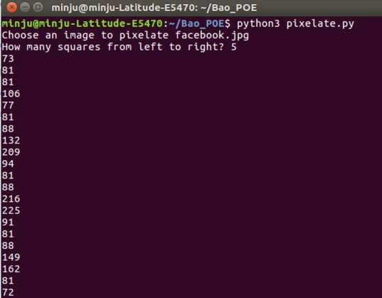
avg_Gray = int(round(0.2989 * av_r + 0.5879 * av_g + 0.1140 * av_b))
print(avg_Gray)
Now, run the main script. The code sets filename as what user inputs after asking on the command line. After user inputs the filename, load the image as img. Then, calculate the dimensions of each chunks (or small images). The code sets num_cols as what user types after asking. Then, calculate the number of pixels for small square by dividing the size of an image (img.shape[1]) by num_cols. In the similar way, calculate num_rows and square_h. After that, convert the image into grayscale image. Then, display the image. After displaying an image, the code saves the file as file_pixelated.jpg. The code splits the filename string by ‘.’ and save it as filename_parts. Filename_parts would be consists of two strings: ‘filename’ and ‘jpg’. Then, the code picks up ‘filename’ and adds ‘_pixelated’ after ‘filename’. After that, add the components of filename_parts (now it is ‘filename_pixelated’ and ‘jpg’) with ‘.’ and set the filename as ‘filename_pixelated.jpg’. By using misc library, save the image.
if __name__ == "__main__":
try:
filename = sys.argv[1]
# save user's input on cmd line as filename
except IndexError:
filename = input("Choose an image to pixelate ")
# if there's no input with keyboard, ask what image to pixelate
img = load_img(filename)
# load the image
# Figure out the dimensions of each square
num_cols = int(input("How many squares from left to right? "))
# width of the square
square_w = float(img.shape[1]) / num_cols
# determine the row number based on the width of the square
num_rows = int(round(img.shape[0] / square_w))
# height of the square
square_h = float(img.shape[0]) / num_rows
# overwrite each square with the average color, one by one
# basically, part of an image is colored as average color
# call function for entire image
for row in range(num_rows):
for col in range(num_cols):
make_one_square(img, row, col, square_h, square_w)
# convert the image into gray scale
# if you want to use rgb image, just comment this line out
gray = rgb2gray(img)
# show the image
plt.axis('off')
plt.imshow(gray, cmap='gray')
plt.show()
# save the image as filename_pixelated
filename_parts = filename.rsplit('.', 1)
filename_parts[0] += '_pixelated'
filename = '.'.join(filename_parts)
print("Saving Pixelated Image")
misc.imsave(filename, gray)
Sprint 2 - Image Processing
11/12/2017
Written by Minju Kang
For sprint 2, we wrote python code that pixelated an image, converted the image into grayscale, and displayed the grayscale value of each image. The code takes the specified n x n, breaks the image up into those sections, and finds the average value for that small block.
Then, we map these grayscale values (0 - 255) to arduino’s position values (0 - 180) and move the arduinos based on that. For this sprint, we had to write those grayscale values manually in Arduino. However, next sprint we will have automated the process overall. In other words, we will try to make python code to automatically dump the grayscale values to Arduino’s serial monitor.
Sprint 2 - Arduino Code
|
11/11/2017
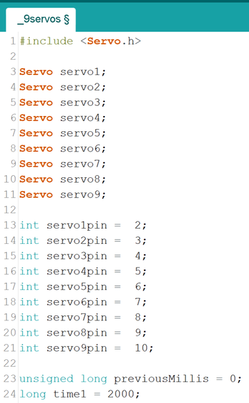
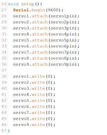
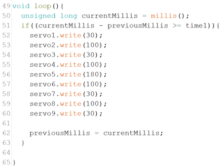
Written by Sarah Our Arduino code in this sprint is very simple. We just wanted to figure out how to get the servos to move. At first, we used the Sweep example function, but we realized that by using delays, we couldn’t make the servos move simultaneously. We found out that we can use the millis function just like in the Blink without Delay example. We start by declaring our nine servos and setting their pin numbers. This is clearly repetitive and as we edit our code moving forward, we want to integrate a class for the servos that allows us to set all of these attributes more succinctly. For now, we set time1 to 2 seconds so that we could clearly see the servos start at the initial positions and then move to new positions after 2 seconds. In future iterations, we want to have a button, either physical or on a GUI that cycles between different images. Next, in the setup part of the code, we begin our serial monitor and also attach each of the servos that we declared above to their respective pins. Our servos are numbered left to right and top to bottom, respectively, so that the upper left servo in the array is 1 and the bottom right is 9. Again, these parts are repetitive, which we want to fix, but we’ll need to learn some new skills in Arduino to do this. In the loop, the first thing we do is check how much time has passed. If it’s been at least 2 seconds, the servos move positions. The values written to the servos create a plus sign shape. The servos in the four corners move 30 degrees, and the vertical and horizontal middle row servos move 100, except for the center pin which moves 180. |
|
Sprint 2 - Pin Design
11/9/2017
Written by Miguel and Hanna
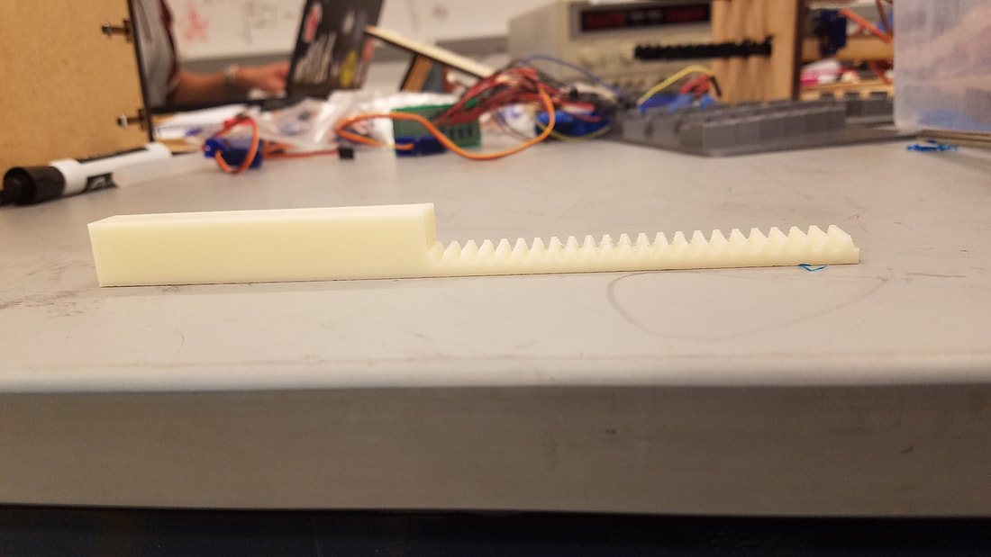
For the pins that make up our art array, we decided to first use Legos as a prototype, then upgrade them to something permanent later on. During Sprint 2, we designed and printed 3D modeled pins, as seen below.
Written by Miguel and Hanna
For the pins that make up our art array, we decided to first use Legos as a prototype, then upgrade them to something permanent later on. During Sprint 2, we designed and printed 3D modeled pins, as seen below.
|

|
Sprint 2 - Servos
11/7/2017
Written by Kai and Sarah
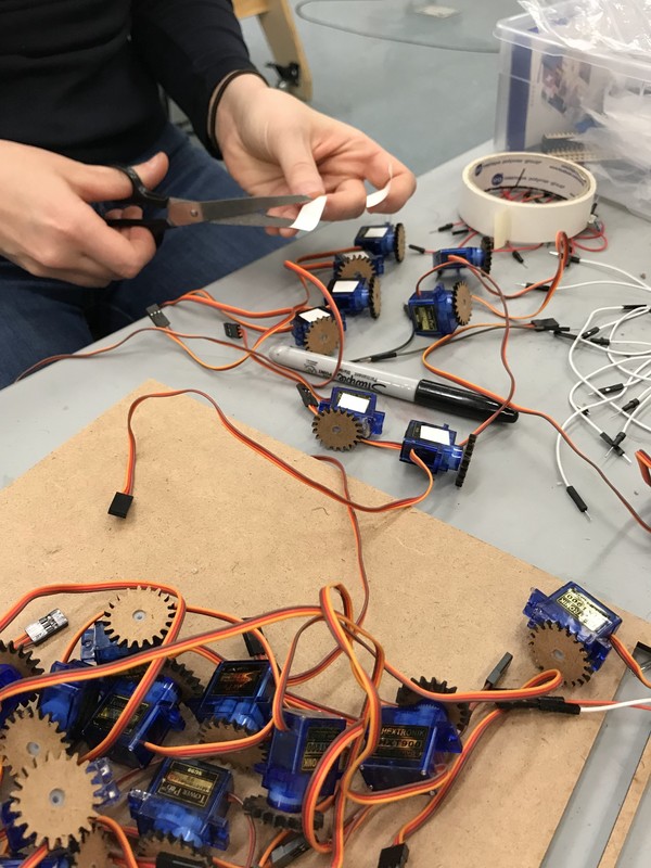
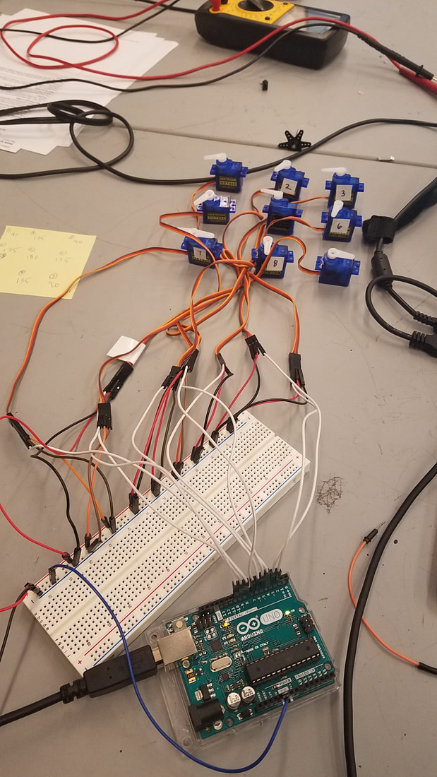
This sprint, we obtained eight mini servos, and ordered an additional 10, so we were able to start working on our pin array. Mostly Kai and Sarah were working on the motors this sprint. We started by placing them in a grid on the table to see if we could get the servos to move to different positions. We initially ran into some trouble powering the array, since the Arduino cannot provide enough current for nine servos. We learned how to use an external power source set to 5 volts and 3 amps to power the servos.
Currently, we are working on our code to control the array. At the moment, the positions for each servo are coded individually, but eventually we are going to take an array from the image processing code and input it into the servos. One of our goals is to make more succinct code that isn’t as repetitive as it is currently.
Written by Kai and Sarah
This sprint, we obtained eight mini servos, and ordered an additional 10, so we were able to start working on our pin array. Mostly Kai and Sarah were working on the motors this sprint. We started by placing them in a grid on the table to see if we could get the servos to move to different positions. We initially ran into some trouble powering the array, since the Arduino cannot provide enough current for nine servos. We learned how to use an external power source set to 5 volts and 3 amps to power the servos.
Currently, we are working on our code to control the array. At the moment, the positions for each servo are coded individually, but eventually we are going to take an array from the image processing code and input it into the servos. One of our goals is to make more succinct code that isn’t as repetitive as it is currently.
Sprint 1 - Reflection
11/3/2017
Written by Sarah
Last Friday, we had our first sprint review and got some great feedback from our instructors and peers. The majority of questions were about the kind of motors we were going to use and how they were going to be positioned. Currently, we’re using Servo motors, which are quite large, and fitting them on our 3x3 array means that the pins will be spaced far apart. This week, we’re going to test out some different motors and see if we can use smaller motors that can be positioned more compactly. This will probably involve figuring out how to wire the motors to our motor shield, and determining how the new motors will change the pin heights. If we use DC motors, our initial idea is to have all motors run for the same amount of time, but at different speeds.
According to our feedback during the design review and from our feedback form, the major concern is that starting with a 3x3 array will only allow us to represent very basic shapes and not complex art like we want. Our main goal for the next sprint is to hopefully finish the 3x3 array, which will give us an idea of how feasible it is to expand.
After the sprint review, we also talked about our end goal. For this first iteration, we had an IR sensor to move the pins up and down. However, we decided together that using the sensor values as input wasn’t the best way to approach the project. Instead, we are going to take image files and convert that image into the pin heights. This way we can easily change art pieces and even have users choose their own image file. Since this is now our new approach, Minju is starting to draft some of the image processing code, so that we can use it to control the motor.
We also reviewed our team health by generating a “pluses and deltas” list, where we comment on aspects of the teams that are going well and that we want to change. From this discussion, we concluded that our Kaizen (the aspect we want to focus on) for this sprint is meeting more often in smaller subteams, but not necessarily always the same small subteams since we all want to learn new skills. We plan to update each other on the subteam’s progress through Slack.
Sprint 1 - First Prototype
10/26/17
Written by Kai and Minju
Our main project goal is to have a system that can scan 2D images and create a raised 3D representation with pins of adjustable height. We want the pins to stay in place once raised, so that the system can be touched without collapsing. Ideally, the pins will be arranged in a dense grid to provide higher resolution, but we have yet to determine exactly how far we can take the project given our time and budget constraints.
This past week, we worked on detailing our plans for the mechanical, electrical, and software systems in our project. We spent some time brainstorming specifics of how we wanted our final product to look and behave, including determining pin “locking” mechanisms, potential motors to use, and whether we wanted the system to stand vertically or horizontally.
We decided to start with a rack and pinion mechanism to raise the pins. For proof of concept, we set up a first-pass system with a single static (non-scanning, for now) IR reflectance sensor and a single “pin” made of legos attached to a servo motor. We had first considered using linear actuators to move the pins up and down. However, with limited budget for our project ($250 in total), we had to find alternative method of moving the rods linearly since the linear actuators we researched were very expensive.
We initially built a rough cardboard model to support the pin and servo, then replaced it with a more polished laser-cut structure. We also will eventually 3D print the rack and pinion structure instead of using Legos so that it will be sturdier.

|
|
Our code determines pin height by translating the IR reflectance sensor reading (which differentiates only between light and dark) into an angle of rotation (varies from 0 to 180) for the servo attached to the pin. The IR sensor reading value is from 0 to 1023, a higher value indicating that the sensor is reflecting on a darker surface. By doing so, we were able to control our motor’s behavior based on IR sensor reading. Eventually, our goal is to control the motor’s behavior based on images that it reads.
The next step will be to incorporate multiple pins and create a scanning mechanism for the IR sensor to return values for a full image rather than a single reading. We are also exploring the possibility of using much smaller servos since we want to use many of them, though there are different types of small motors we could potentially use.
The next step will be to incorporate multiple pins and create a scanning mechanism for the IR sensor to return values for a full image rather than a single reading. We are also exploring the possibility of using much smaller servos since we want to use many of them, though there are different types of small motors we could potentially use.