How To
How To
How to Make it
Materials
For our complete bill of materials and prices for each item, check out our finances page.
Building The Mechanical Structure
To build this project, you will need access to a laser cutter and a 3D printer. We used Epilog Helix 24 Laser cutters, and Makerbot 3d Printers. You can find and download the CAD files and cut sheets on our github. Our cut sheets will work best with a laser cutters that have a bed of at least 24" x 16", but our parts are possible to cut on a laser cutter with a bed as small 14"x14", but that would require making your own cut sheets. .
Acrylic Boxes
Once the parts have been created, there is a bit of fabrication left. The acrylic boxes are put together with acrylic adhesive (i.e. create butt joints between the sides of the walls), except for the press fit puzzle box side of the electronic box, which is meant to be removable. Once you do a first pass at gluing, test them for waterproofness. There will likely be some leaks, in which case you should keep adding more acrylic adhesive until no water slips through the cracks. Remember to let the adhesive set before you test it!
Base
Almost all of the MDF pieces can be assembled by press fitting the pieces together, along with the acrylic water ramp. We added acrylic rails to the ramp to guide the water so it does not seep into the MDF on the Edges. We used small strips of scrap for this, and do not have CADed pieces. A rubber mallet will make the press fitting process much easier! The flexible pieces of the shade need to be wood glued together, and then it just sits on top of the panel with the lights on it, so that the shade can be easily removed to access the lights.This panel just sits on top of the copper pipe. The pipe mounts will need to be screwed onto the top corners. The next thing you should do attach the aesthetic cover of the box, which will need to be wood glued. Now the last step with the mechanical structure is to attach the push button. We decided to add this feature after lasercutting the back panel, and had to drill holes and then file them down to the shape of the push button. you could avoid this by adding in the hole before laser cutting.
Constructing The Electrical System
Once the box is fully assembled it is time to add in the electronics!
Light and Moisture Sensors
You should start off with soldering the soil moisture and light sensors. They each need a wire for Ground, Power, and Signal, eacho of which should be about 2 feet long, and then braided together after soldering. These all are fed through the holes on the top of the base, and then in through the holes in the back of the electronics box. once they are through that hole, they are ready to be soldered to a proto board, to join all of their power and grounds.
Lights
Next comes the lights. these should be split apart into 4 strings of 5, and then re-soldered. the end of them will need 3 wires, which will be braided together, just like the sensor wires. These wires should be about 3 feet long. Attach the lights to the bottom of the light panel in a square, using double sided tape or an adhesive of your choosing. Then the wires get fed through the pipe, and down into the electronics box. The lights gare powered with an external power source, so you should solder the power of the light wire to the power of an external 5 volt source. The grount of the lights should be soldered to both the gound of the external power source as well as the ground of the light sensors.
Pump
The pump should have a red wire and a black wire. You should attach these two wires to the M1 position in the motor shield which is on top of one of the arduinos.
Water Level Sensor
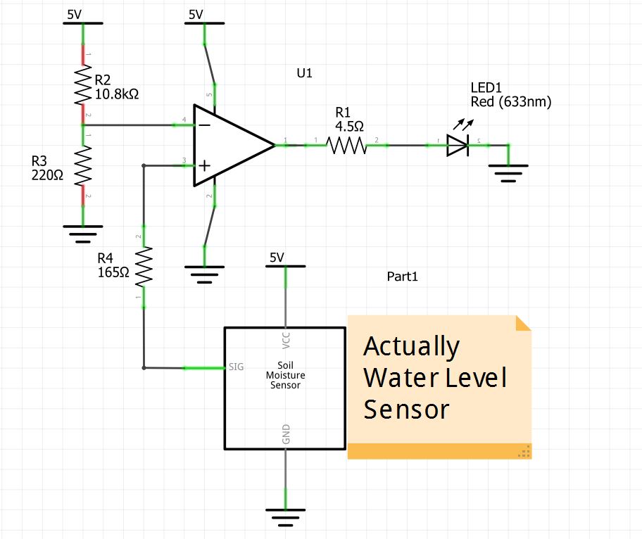
Solder the circuit according to the following diagram on the left.
Attach the Arduinos
Make sure to attach the arduinos together using the diagram found on the Wire library's page here.
The Software System
Use the instructions in our github readme to download the necessary files and run the code to the arduinos and then the code for the GUI!