Electrical
The main responsibilities of the Electrical System was to use a pressure sensor to detect if a player stepped on the arrow pad and change the color of the arrows accordingly. If the player needs to step on an arrow, then that arrow turns blue. If the player stepped on the arrow in time, then the arrow turns green. If the player does not hit the arrow within the time frame, then the arrow pad turns red. The two main components in our circuit diagram were the pressure sensor and the strip of LED lights. The code used to control the Arduino that does this can be found here.Pressure sensor
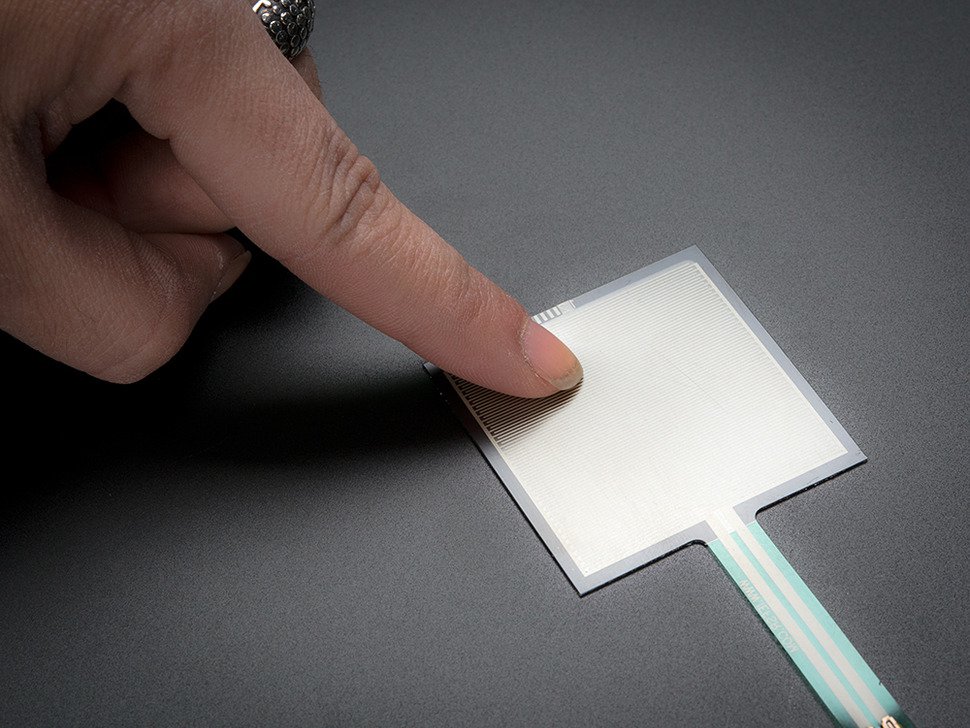
We bought Adafruit's Square Force Sensitive Resistor - Interlink 406. This square sensitive resistor functions like a resistor that changes values with pressure. Inside it has a voltage divider with a fixed resistance on one side and a variable resistor on the other side to read the force. The middle node of the voltage divider connects to a non-inverting amplifier, and the output of the operational amplifier is the output of the pressure sensor.

pressure sensor.
When we connected the pressure sensor to the Arduino, we used Arduino C to read the pressure. The pressure ranges from 0 to 1000. The higher the output, the greater the pressure. Through calibration, we discovered that a pressure of 950 was a good threshold value to detect steps and eliminate noise. In the code, we checked for the pressure value to detect if the player was stepping on a pad. More information on the software library for this pressure sensor can be found on Adafruit's website. More about the software logic will come in a later section on this page.
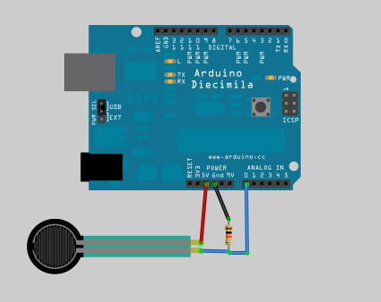
Pressure sensor circuit schematic.
LED Strip

We bought the Adafruit Neopixel RGB LED Strip. This is a string of Light Emitting Diodes or LEDs for short.Each light has a red LED, blue LED, and a green LED. In software, we programmed the red-green-blue, or the RGB value. We could control which light in the strip held which specific value. We could also program the brightness of the entire LED strip. The string of LEDs drew more power with a higher brightness requirement. We ran into the problem that the Arduino could not power all of the 60 LEDs at the default maximum brightness. We acknowledged the trade offs between brightness and power. Therefore, we reduced to a brightness by half in software and added a 12kOhm resistor between the Arduino and the input to the LED strip. A resistor is a passive electronic component that decreases the current that the LED strip required. Our circuit to power the LED strup is to the right.
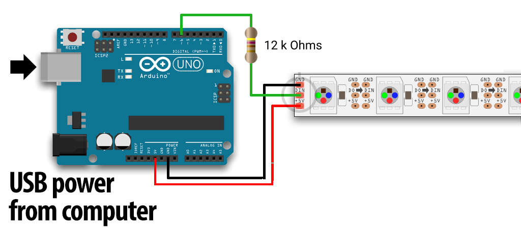
LED strip circuit schematic.
Integrating the LED and the Pressure sensors for one arrow piece
We wanted the pressure sensor to control the colors in the LED strip. We used an Arduino to control both of them. Below is the circuit diagram for just one LED strip and one pressure sensor.
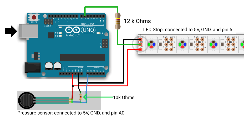
Circuit diagram with one LED strip and one pressure sensor.
After we connected these two together, we wrote the software logic to control the LED strip changing colors on one arrow piece. When the Arduino receives information that the player needs to click on this arrow piece next, then the LED strip would turn blue. The blue was alerting the player that they need to hit this specific arrow piece next. They have about 3000 milliseconds to step on the pad. The Arduino waits 3000 milliseconds. If during that time, the pressure sensor sends a pressure greater than 950, then the Arduino considers this pad pressed. At this moment, the Arduino makes the LED strip for the arrow piece green as a form of a good job recognition. If during those 3000 milliseconds, the Arduino does not receive a pressure greater than 950, then it concludes that the player did not step on the pad in time. Therefore, as a signifier that the player missed it, the LED strip turns these LEDs red.
Obstacles
The LED strips came with 60 LED lights in one strip. We have four arrow pieces. We bought 4 strips, thinking we could cut the strip and use 30 lights per arrow piece. When we tried to solder the 30 - 60 lights in the strip together, we likely produced cold soldering jobs. The LED strips are 12.5mm wide. There were three tiny pads to solder onto, the left one was ground or 0V, the middle one was the input, and the outer one was 5V. This was really difficult to do with the soldering pen found here at Olin.

We also encountered the obstacle where the pressure sensors would constantly display that they were over the threshold pressure sensor. When we accidentally rattled the wires, we gathered that perhaps there was something wrong with our coop of wires or that because there were so many wires tangled together, their electromagnetic waves could interfere with each other. Our approach was to make each arrow piece modular. First, we took each arrow piece and twisted all of the wires together. Then we found connector pins that allowed them to plug into wires connected straight into the Arduino. Both of these things were helpful in reducing the noise.
Final circuit
Due to our electrical limitations, we pivoted from our MVP. We planned to have four arrows with four pressure sensors, and each arrow change colors according to the player's response to the arrow. We still have all four pressure sensors detect if the player stepped on the pad. However, now instead, we only have one LED strip. Our circuit schematic looks the following.
 Final Circuit Schematic with four pressure sensors and one LED strip