Sprint 3
Almost at our MVP, accompanied by two redesigns
Sprint goals
- Get to MVP
- Stay motivated!
- Use class time more efficiently
Current MVP
Have an automated curtain of water that displays a variety of images and designs controlled using a microcontroller, and successfully collects and recycles water to be self-sustaining. More specifically, the scale of our MVP is 4 nozzles, printing simple designs, but functioning well!
Lessons Learned
This sprint we learned not to be afraid to kill our darlings. Sometimes stepping back helps you step forward. We also learned to not take suggestions at face value, and to explore all options before immediately settling on one because it was suggested to us. We learned how to manage relationships with outside stakeholders well! Finally, we truly learned how to hustle and get stuff done.
Almost at MVP
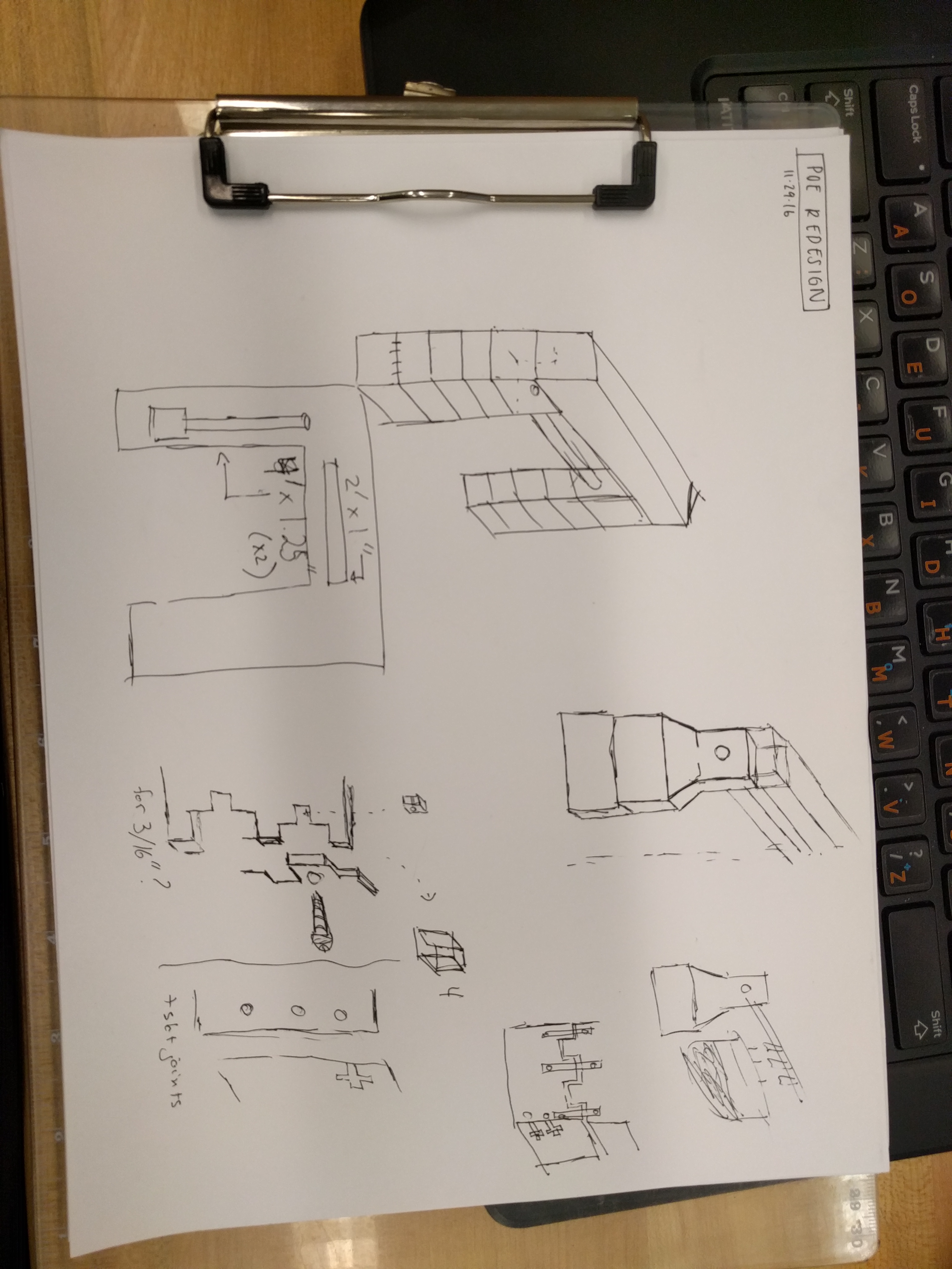
This sprint, we almost hit MVP, despite two redesigns. A rough sketch of our original design can be seen below.
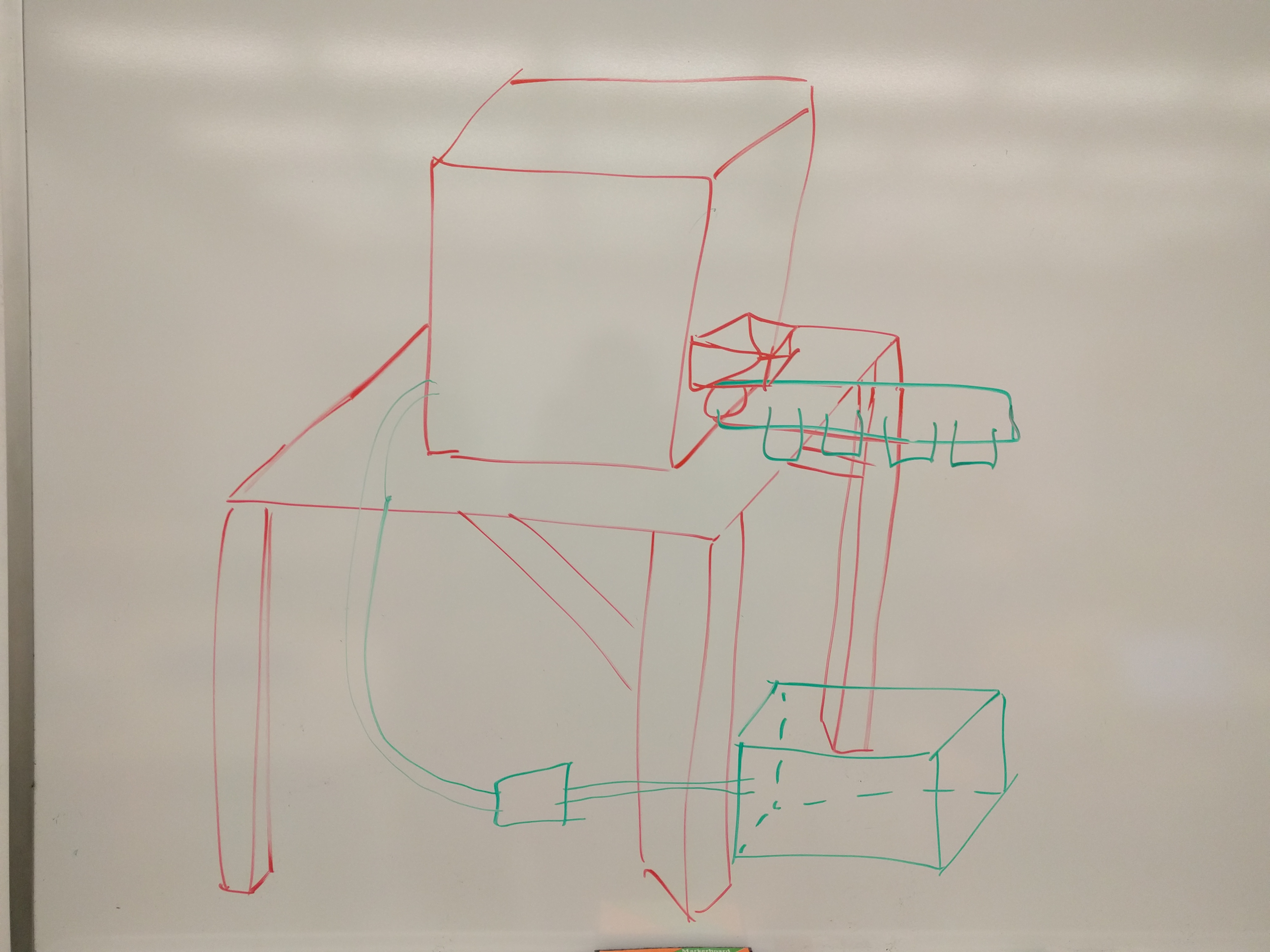
We determined that the original system that we designed was somewhat unstable. It also relied heavily on gravity in order to give us the pressure necessary for our system. In our second design, we combined the water distribution and collection system with a single constant flow pump. We then designed the system below. This also created a much more stable system, in which there isn't a huge bucket of water 5 feet above the ground. This also lessens concerns about such a large bucket accidentally getting knocked over.
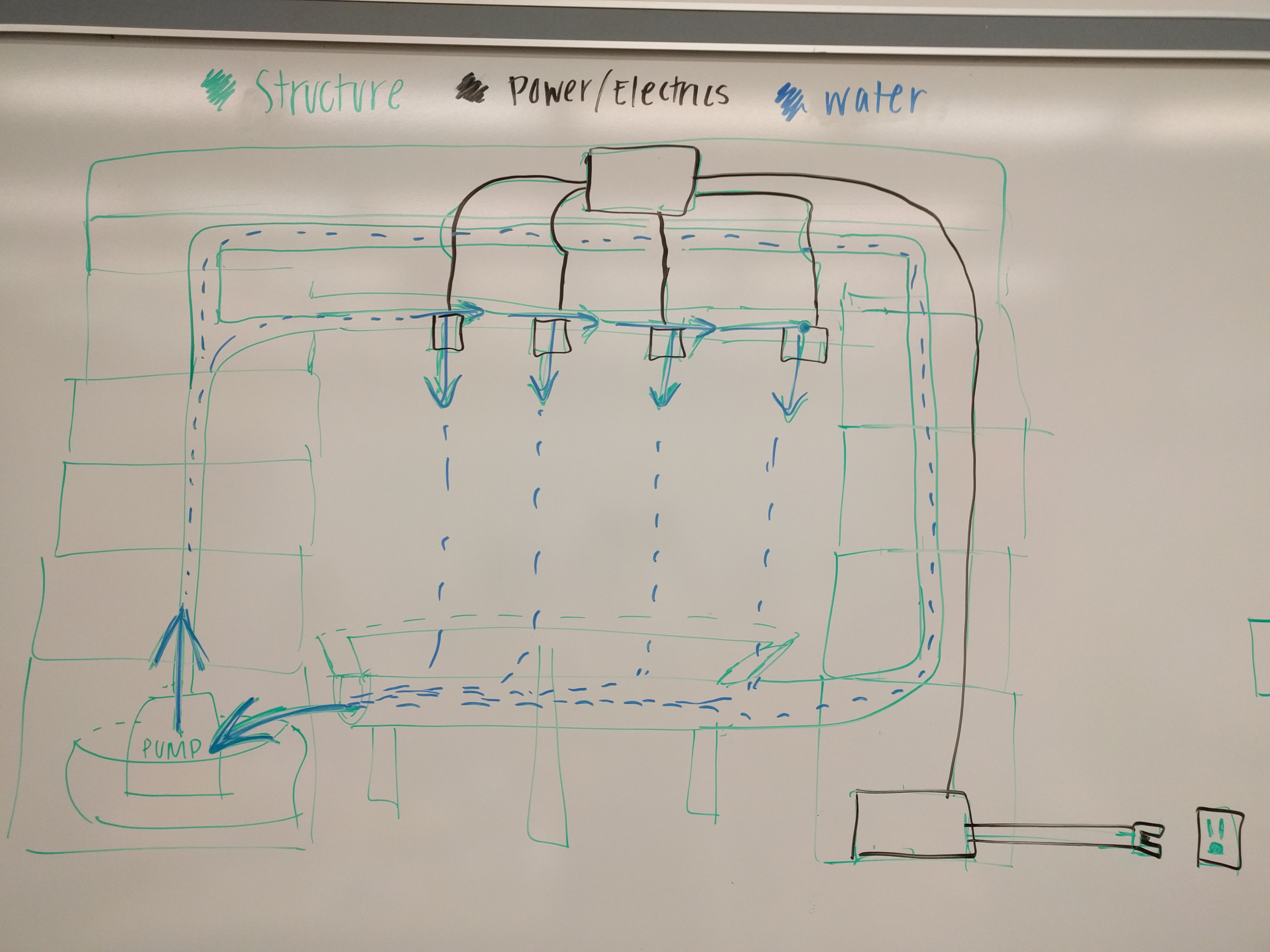
Finally, we wanted a more modular cabinet system. We designed blocks that were able to be stacked, and designed them so that they would not tip over and many could be printed and assembled at once by lasercutting them, which created a stable design that we could quickly assemble. We also added an overflow pipe in order to mitigate extra water pressure from the pump, which would cycle back into the water collection system.
We also began construction on this updated design. We were able to assemble everything except for our housing. This includes making a huge push to create 4 actuating nozzles. We did not include the cabinet or overflow pipe. The need for such things can be seen from watching the following videos. Because we used a constant flow pipe, a tremendous amount of pressure is built up over time. With an overflow pipe, we should be able to maintain the amount of pressure that we want more sustainably. We also had not yet fully CADed by the cabinet design by the time that these videos were recorded. The first video of the pipe system and water collection and distribution system can be see in the video below. Note that all of the solenoids were left open and no nozzles were used during this video.
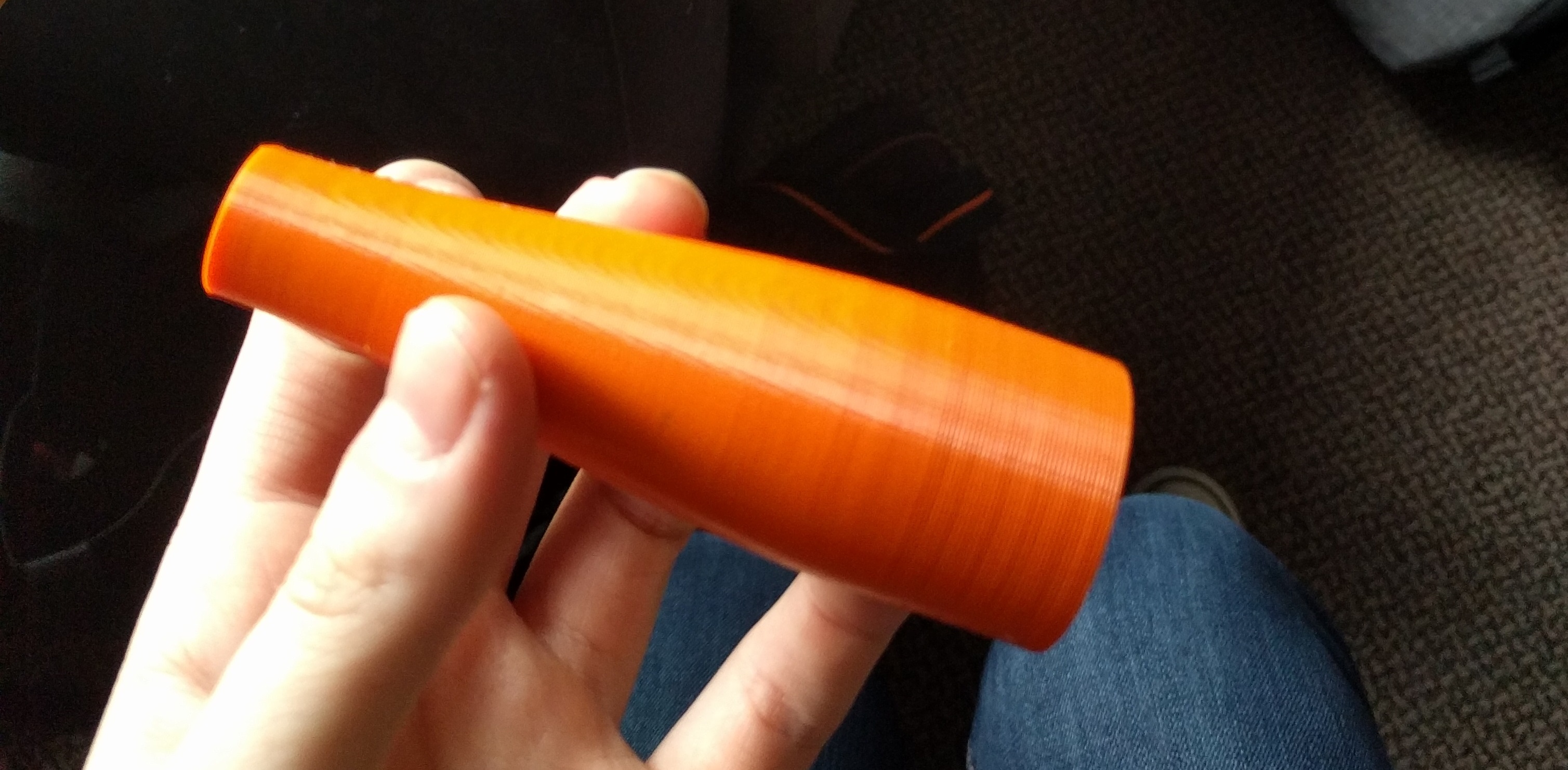
This second video demonstrates the laminar flow created by the nozzles put on top of the solenoid valves. The orange nozzle on the left was printed with the Stratasys, while the black nozzle on the right was printed on the MarkForged printer. It should also be noted that we primarily printed the orange nozzles for our final product for the purposes of time, although we found that they generally performed approximately the same as the MarkForged nozzle. This video partly demonstrates our control over the system by our ability to actuate all the nozzles at the same time. The next video will further demonstrate this.
In this final sprint 3 video, we were able to demonstrate our control over the system by actuating nozzles on and off at different times, how we would expect it based on the code. This is a final validation for our electrical and software systems.
Mechanical Progress
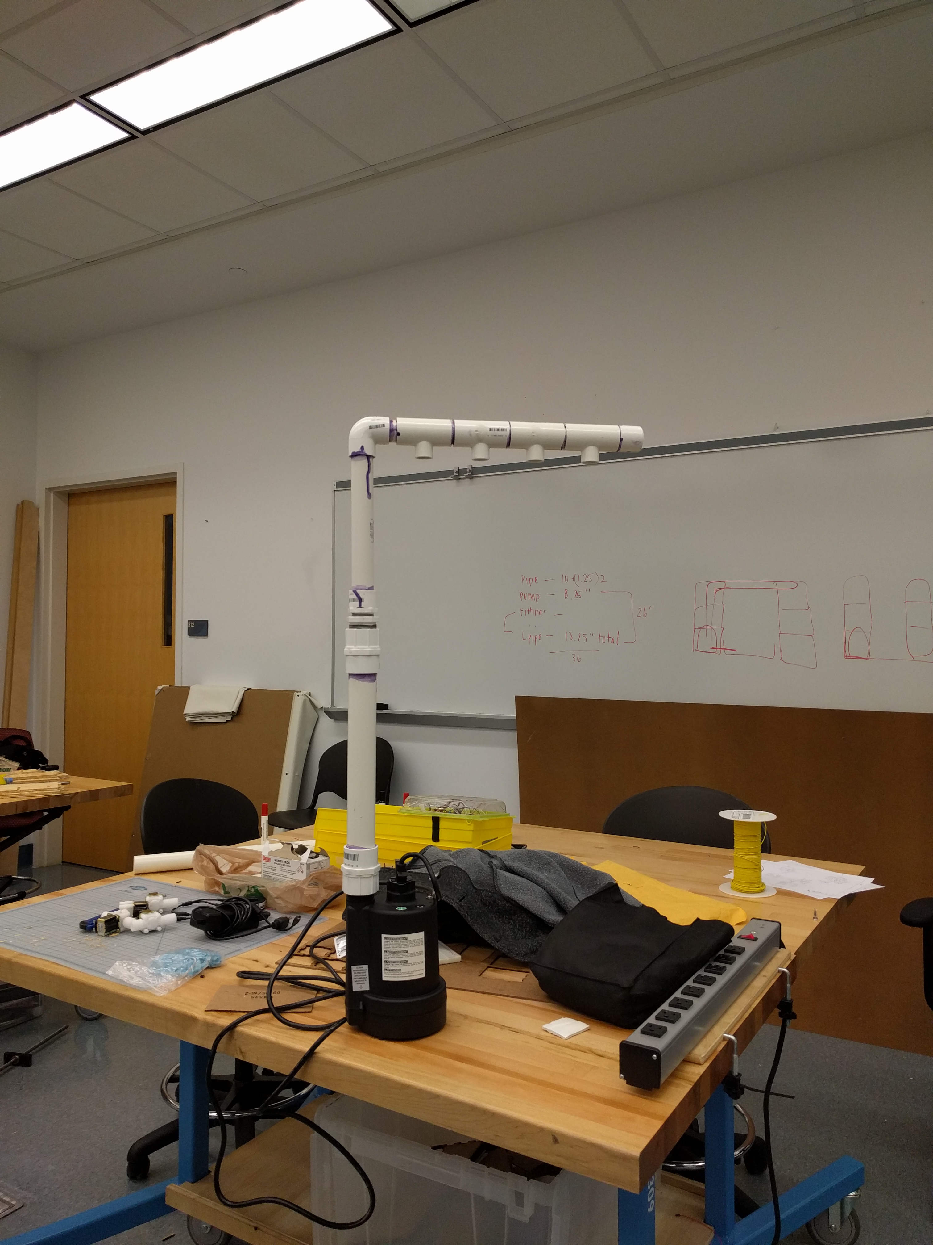
This sprint we were able to validate the size of our pipes. This was our first prototype with PVC connected to our nozzles and an integrated system of multiple nozzles in line. Although we haven't yet validated our overflow pipe or cabinet, we CADed and began to lasercut the cabinets.
Electrical Progress
We have everything except for the power supply. Circuit designed, and all four nozzles correctly actuating using shift registers and a makeshift powersupply. Incorporated mosfets.
Software Progress
Basic four nozzle patterns made using python code that interacts with arduino code and writes a byte to serial on the arduino. This then controls the corresponding nozzle. Manually input patterns were able to be created and tested on our four nozzle system.