Systems and Subsystems
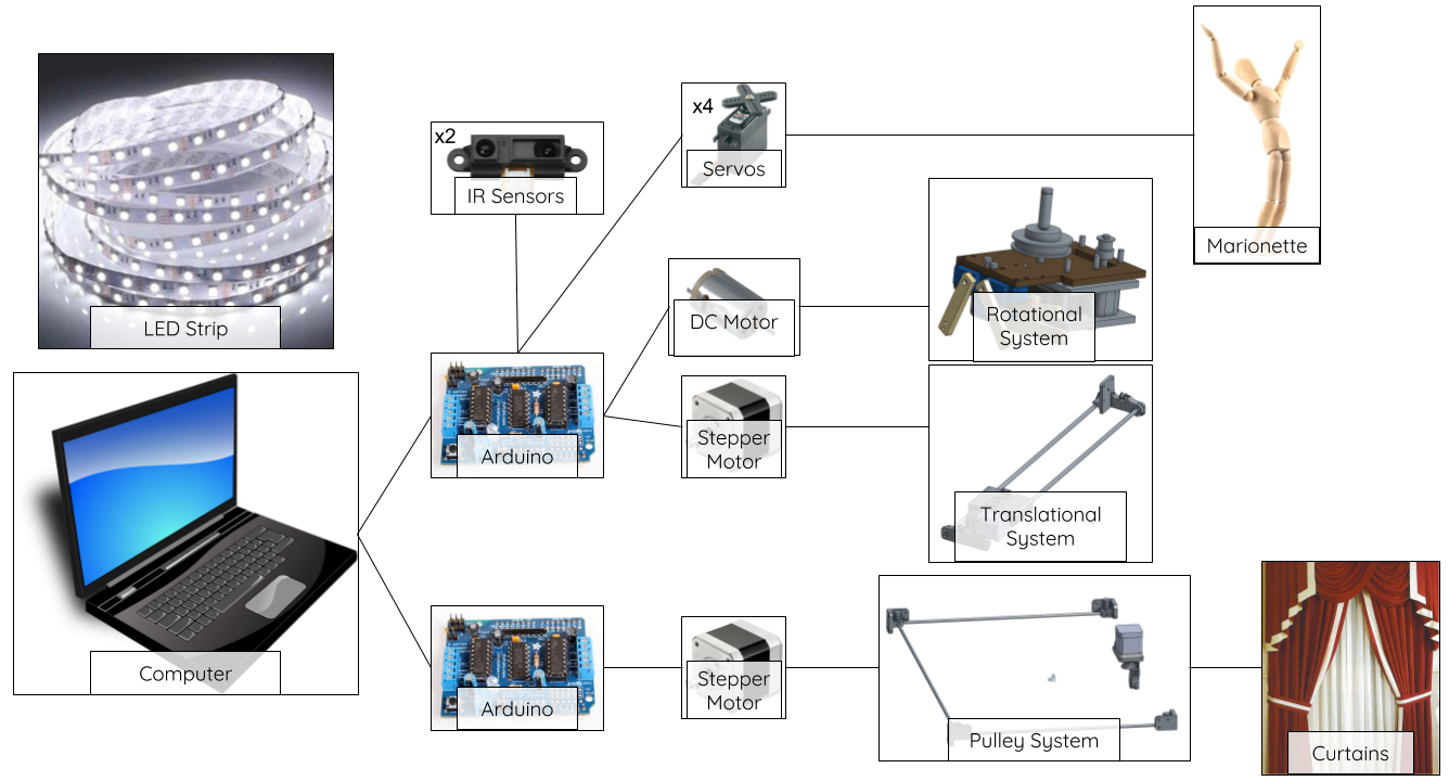
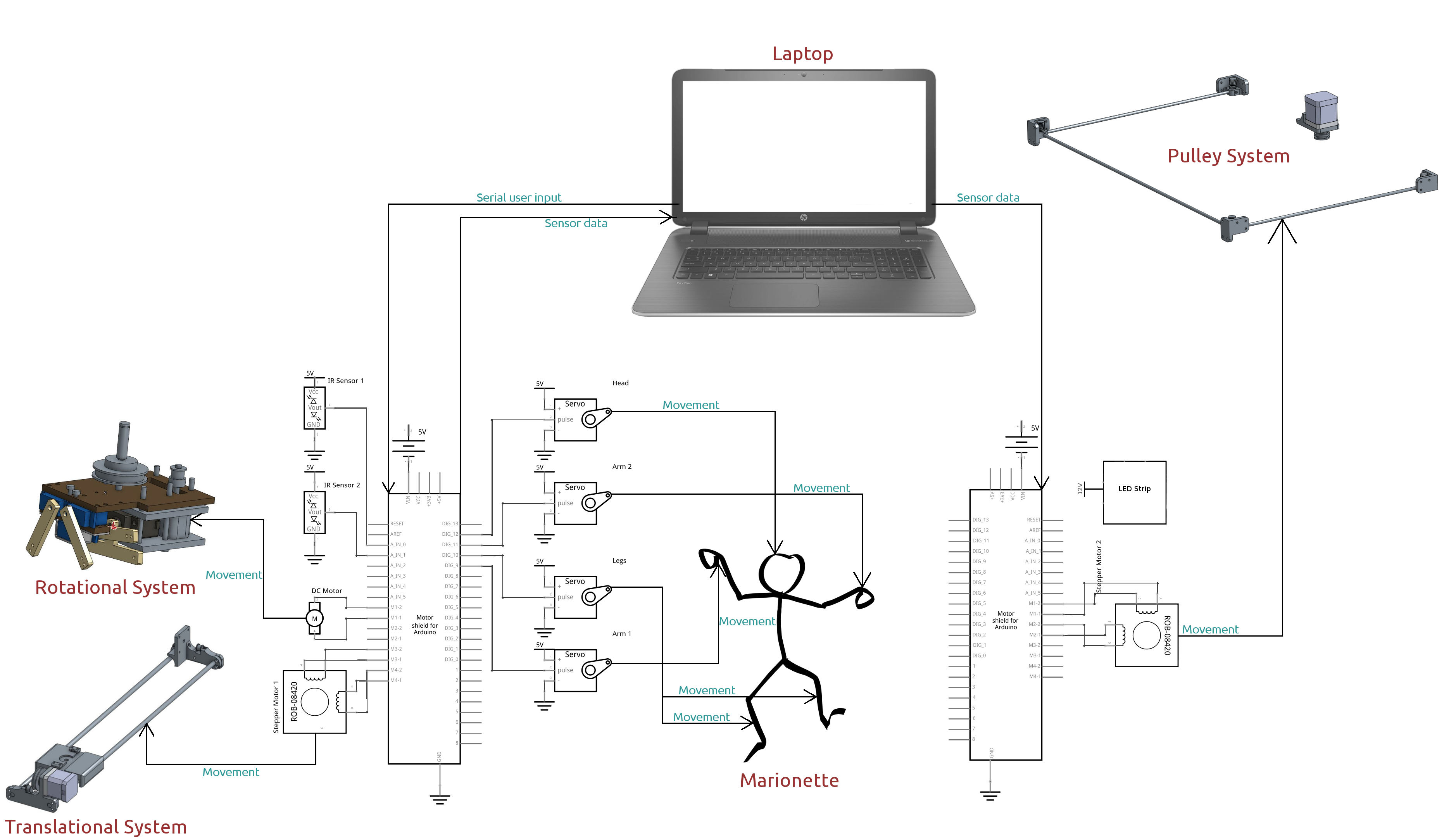
There are several main systems in our project. These are depicted above in a somwhat more pictoral fashion, and again below in more technical detail (where red text indicates physical/mechanical components, green text indicates the transfer of commands or data through software, and arrows indicate the direction of transfer). All systems are further explained in the following Mechanical, Electrical, and Software subsections.
The Mechanical System
The name of the game in designing the mechanical components of this project was robustness; we designed and redesigned every piece to be as sturdy as possible. However, we also needed to keep all of our components as compact as possible because our stage isn't very big, and besides, the aesthetic appeal of our project would be diminished if even a single loose wire was visible. As a result, if you take a look at all of our CAD drawings, we hope you notice that each part is designed as space-efficiently as possible without sacrificing any of its intended functionality.
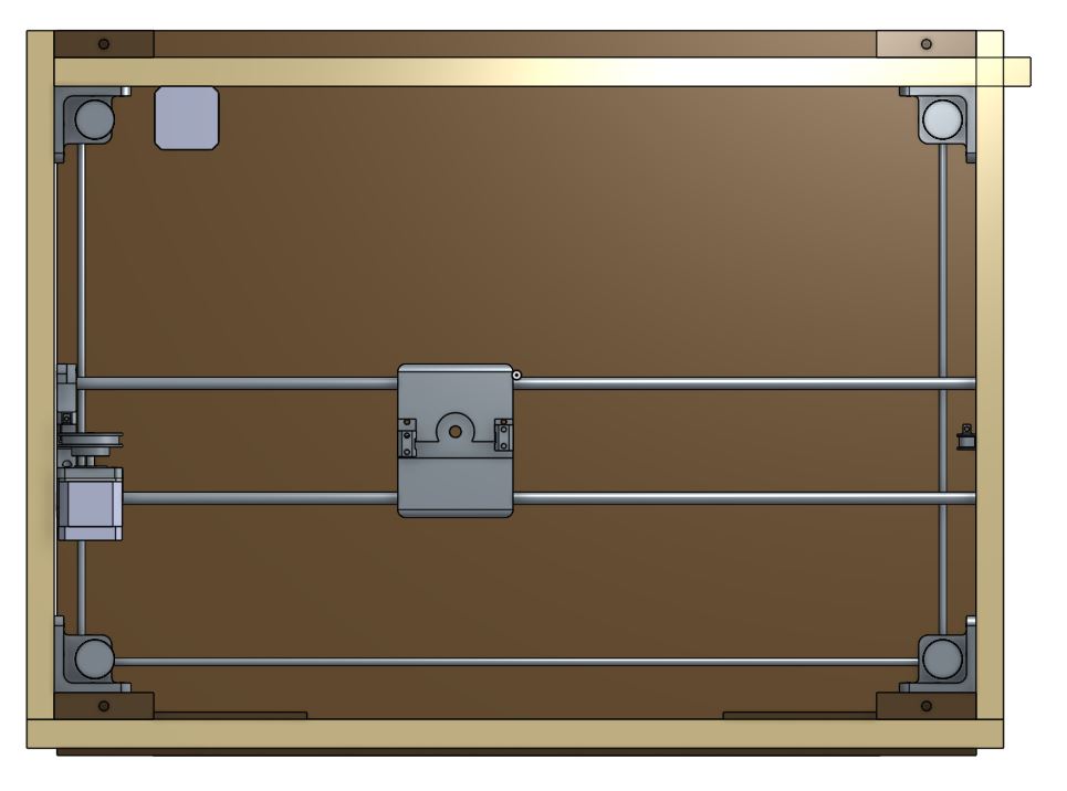
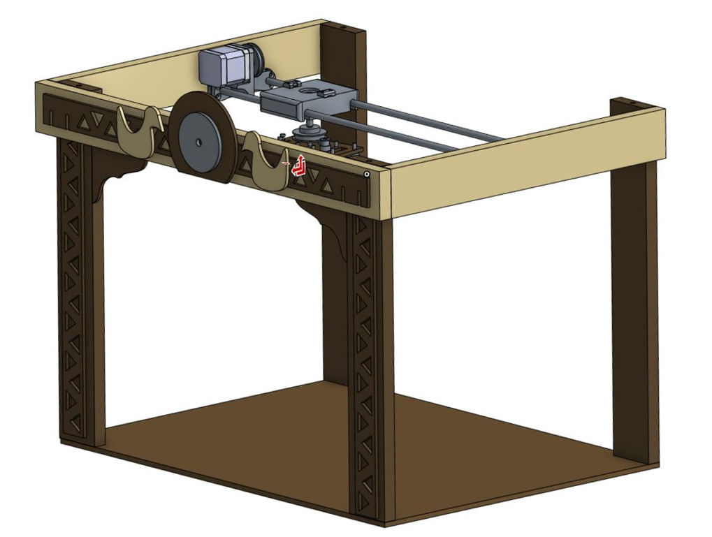
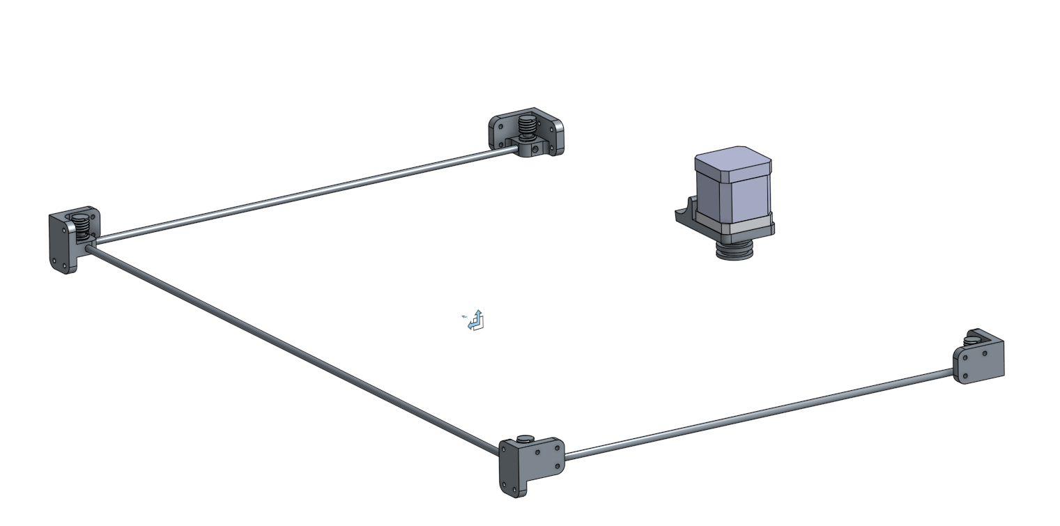
This picture shows a top view of the stage, where all significant mechanical components (the pulleys, gantry, etc.) are visible.
Click any of the CAD drawings below to get a better look, or click below to see our designs on OnShape.
Intermediate Designs
Below are some of the beginning designs we made for various parts of our mechanical system. These worked, at least at first, but we knew we needed to redesign them for better functionality and to make them last. Above is a picture of what we originally envisioned for our stage.
Final Designs
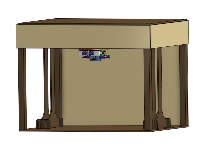
Throughout this project, it was necessary to redesign various parts to keep our mechanical system compact and robust. Our final mechanical designs are as tightly fit and strong as we could make them, providing a solid foundation for our project. Above is a picture of our final stage design.

The First Gantry Design
Our original gantry design was created with the intention of making it able to support itself in order to test translational movement. In this initial design, we had a motor attached to the marionette with wheels attaching the trolley to the gantry.
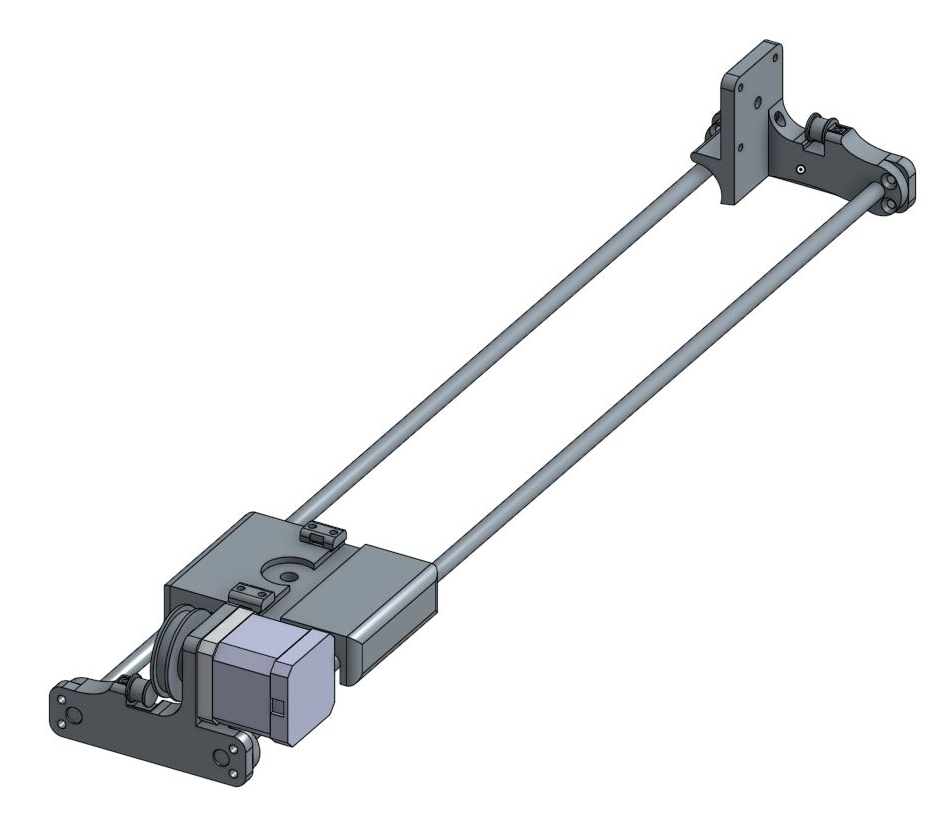
The Final Gantry Design
We found that our original gantry design was too unstable, and redesigned it. Our final gantry design is designed to attach to the stage and pull the marionette from one side to another, using a belt attached to a stepper motor on one side of the stage.
The First Motors Design
At first, we tried a spooling mechanism to raise and lower the marionette, but this required the use of an unnecessarily complicated system of 3 DC motors. The press-fits we designed to attach the spools to the motors were unstable, and we learned that tolerancing 3D printed parts to be difficult but necessary.
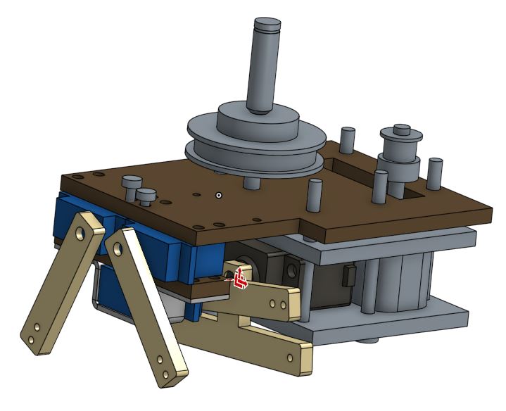
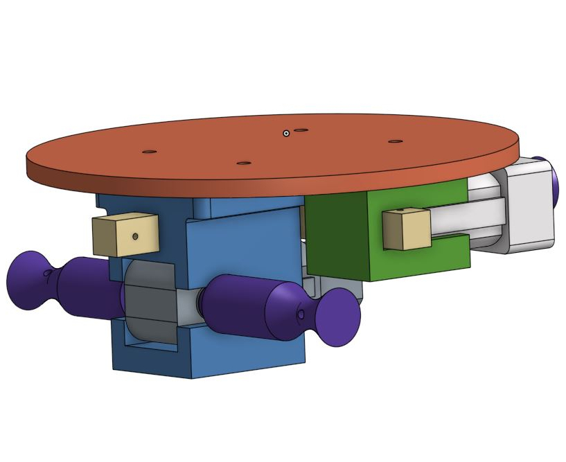
The Final Motors Design
This design proved to be much more adaptable than our previous. We switched from spools to a lever system and inserted more motors, including a motor for the head of the marionette and a motor for rotation, without making too many drastic changes. This design was also more compact than our previous.

The First Trolley Design
The original trolley was designed to connect to our original motor mount. The idea was to have a DC motor drive a wheel that was attached to the gantry.

The Final Trolley Design
Our new trolley is much more robust and easily attached onto our gantry to move the marionette translationally. It's also far more compact than our original design.
The Final Pulley System Design
The original pulley system consisted of four mounts on the inside corners of the stage that housed small 3D printed pulleys with two 1/4” diameter threads and a mounted stepper motor attached to a driving pulley with two larger diameter threads. A tensioned loop of string looped around the entire system to be tied to the curtains mounted on thin acrylic rods that also attached to the motor mounts. It was double looped in such a way that it would drag the curtains open and closed depending on which way the stepper rotated. The PLA pulleys were weak and had a habit of snapping in half as well snagging because they weren’t smooth enough for the string to move easily. The string also crossed over itself a lot because of how it was looped which added even more friction. This meant the large stepper motor pulley couldn’t drive the curtains. We decided to machine new pulleys out of scrap aluminum instead because it’s smoother and stronger. We used a ½-13” die to add threads to the pulleys to keep the string from intersecting when it crossed over itself. The rest of the pulleys were turned down to smooth edges. The stepper motor pulley was made out of better material as well.
The final designs for the pulley can be downloaded here, and for the stepper motor portion of the pulley, here.
The Electrical System
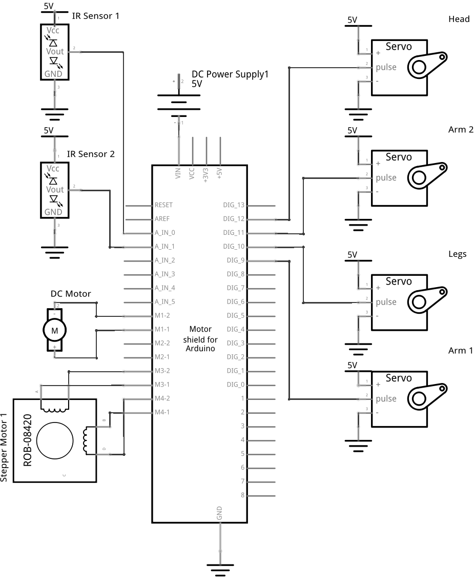
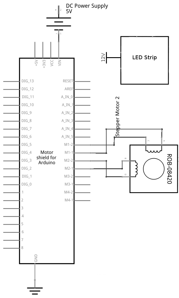
We used two Arduino Motor Shields to control all the components of our project. In the way of motors, we used four servomotors: one for the head of the marionette, one for the legs, and two for the arms. For drawing the curtains and moving the marionette translationally, we used two bipolar stepper motors. Finally, to rotate the marionette, we used a DC motor. We also used two infrared proximity sensors, and to enhance the appearance of our stage, we used a strip of LEDs, which take in their own power supply of 12V.
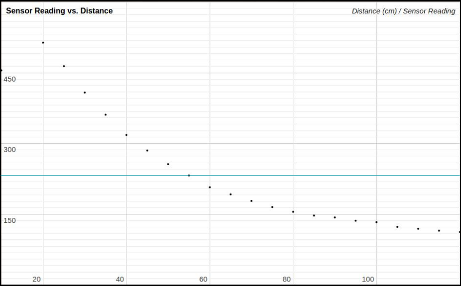
We produced this calibration curve for our infrared distance sensors to determine at what distance an audience can be detected. We decided to set the threshold at around 55 centimeters (the blue line on the graph), since this seemed to make sense in terms of how far away the audience would stand.
The Software/Firmware System
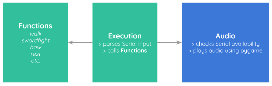
The source code that runs our project can be found in our Github repository. The source code is broken down into two different files. One file contains all the functions that the marionette can perform— walking, bowing, swordfighting, and so on. The other file contains execution capabilities; it allows the user to type in a serial input (a string of commands in the form [String command, int duration; String command, int duration; ...]). The execution file parses commands and calls methods from the functions file to move the marionette accordingly. The firmware is run on two Arduino UNOs with Adafruit MotorShields and is written in the Arduino programming language. We use the Adafruit MotorShield library.
There is also a software component that uses Python's pygame library to play audio files to accompany the marionette's performance. The Python code checks the serial port to see if the Arduino UNO is running, and plays audio files accordingly.
The code is structured to be as versatile as possible, in that a wide variety of movements and audio files can be used (as long as the audio file and movement commands are valid).
Dependencies: Adafruit MotorShield library, pygame library