|
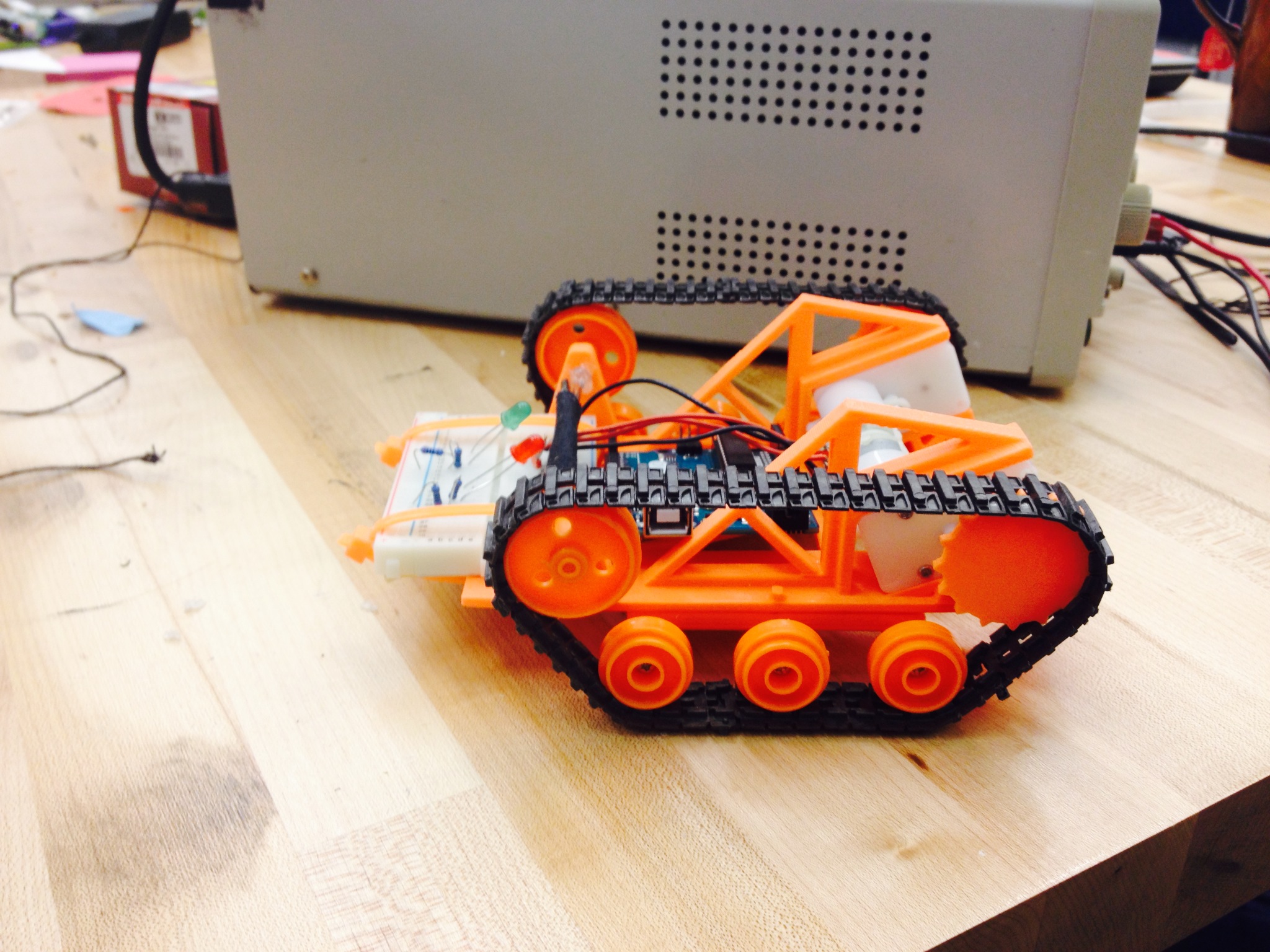
Sprint 1: Our beginning goal was to create small-scale models of what we thought would be our final subsystems, since we did not yet have the parts to start on the creation of the final pieces. The idea behind this was to have a physical system to look back on for quick reminders, and to also have the start for the each subsystem as we began to iterate on them and improve them in future sprints. Our product at the end of this sprint was a mini-robot, with a 3D printed chassis, with fully human controlled motion with an integrated LED-IR distance sensor system. The electrical design for this sprint was intentionally simple, since our main goal was to create a small-scale, easily testable system. We used an Arduino with an Adafruit motor shield to connect to two servo motors, each one controlling a side of the treads that were used in place of wheels on the robot. The other aspect of the system was a basic LED-IR circuit, built on a solderless breadboard, that lit up when the robot was both close to and facing anything. This was meant to simulate the robot detecting a designated target, and displaying some notification that it was armed and ready to act. The power source was actually a laptop computer which the Arduino pulled 5 volts from and then distributed to each component. The mechanical design for this sprint was also quite simple, though we added some interesting components. We opted to use tank treads in place of wheels on our robot, so we found a set of treads that would fit our design. On top of this, we chose to create our own chassis that would fit an Arduino in the middle, as well as interface well with the tank treads and the two servos that would control them. Given our time constraints, we decided that 3D printing was the way to go with the chassis as well. The chassis was designed to minimize the weight, since the servo motors that we had did not generate a huge amount of torque, and the tread system required more than a wheel-based system would. As a result of this, the chassis looks a lot like a frame; we removed as much of the material from each panel as we could while maintaining enough structural stability to support the system. We wrote code on the Arduino to receive a serial input from a computer and adjust the motion of the robot accordingly. The serial output was limited to direction (forward, backward, left turn, right turn) and a stop key. It was sent using a Python program for this purpose. Each input would then go to the Arduino’s serial reading function and the Arduino would choose a motor setting based on that. Since the intent of this first iteration was to be very easy to modify, the integration was necessarily quite simple. The chassis was designed to fit the Arduino and motor shield combination, which was then simply zip-tied to the chassis for easy removal and modification. The breadboard was also zip tied to the front of the chassis. The chassis also held the IR sensor on its front. At this point in the process the whole system was powered by the 5 volt power from the Arduino itself, which was drawing power from the laptop that ran the Python serial output code. This power went to both motors, the IR sensor and to the LEDs through the Arduino (and the breadboard in the case of the LEDs). The integration went off without a hitch, since it was designed to be so simple The power and serial output was sent to the Arduino via a USB cable connected to the Arduino, and the system would respond and move accordingly. The result of this integration was that we knew we were able to control a robot with a serial input from the computer, as well as have it respond to information about a target’s location, two key components of our final design. This sprint also provided us with some proof of concept with the treads, as we were unsure about whether or not they would actually work well. 
Sprint 2: During this sprint, we advanced in leaps and bounds from our previous iteration. The first major step that we took was going from a cardboard and miniature concept to a full scale chassis. The chassis was built out of 0.032 aluminum sheet as were the standoffs for the idler shafts, miscellaneous mounting brackets and the covers. Additionally we began the printing of the treads on the markforged. We were able to print two proofs of concept: the first was to characterize the flexibility of a 0.1 in thick part, the second was to help inform of possible tread patterns for the final iteration. We were hoping to print our first full segment; however, we suffered a major setback due to a clogging issue in the printer’s extruder head. Lastly, we began development of a claw as an add-on to the chassis, to grab onto a close zombie and let the human get away! In terms of software, this sprint was the time for experimentation with different tracking libraries. In the end, we settled on Microsoft's Kinect API, since it was faster and more accurate than OpenCV. As per our sprint goals, we attempted a full integration of software, electrical, and drivetrain. However, we were unable to run the motors as the required current proved too much for our wires. Due to this failure, we decided to add breakers to the system to avoid and future surges as well as move to a better quality wire that we can be sure will be able to keep up with the demands of our powertrain. We hope to be able to run a full integrated test (minus the attachments) once all the mechanical components are fabricated. We believe that this will set us back on the right path to surpass our minimum viable product and create something truly exciting. Additionally, this website was designed and launched in this sprint! 
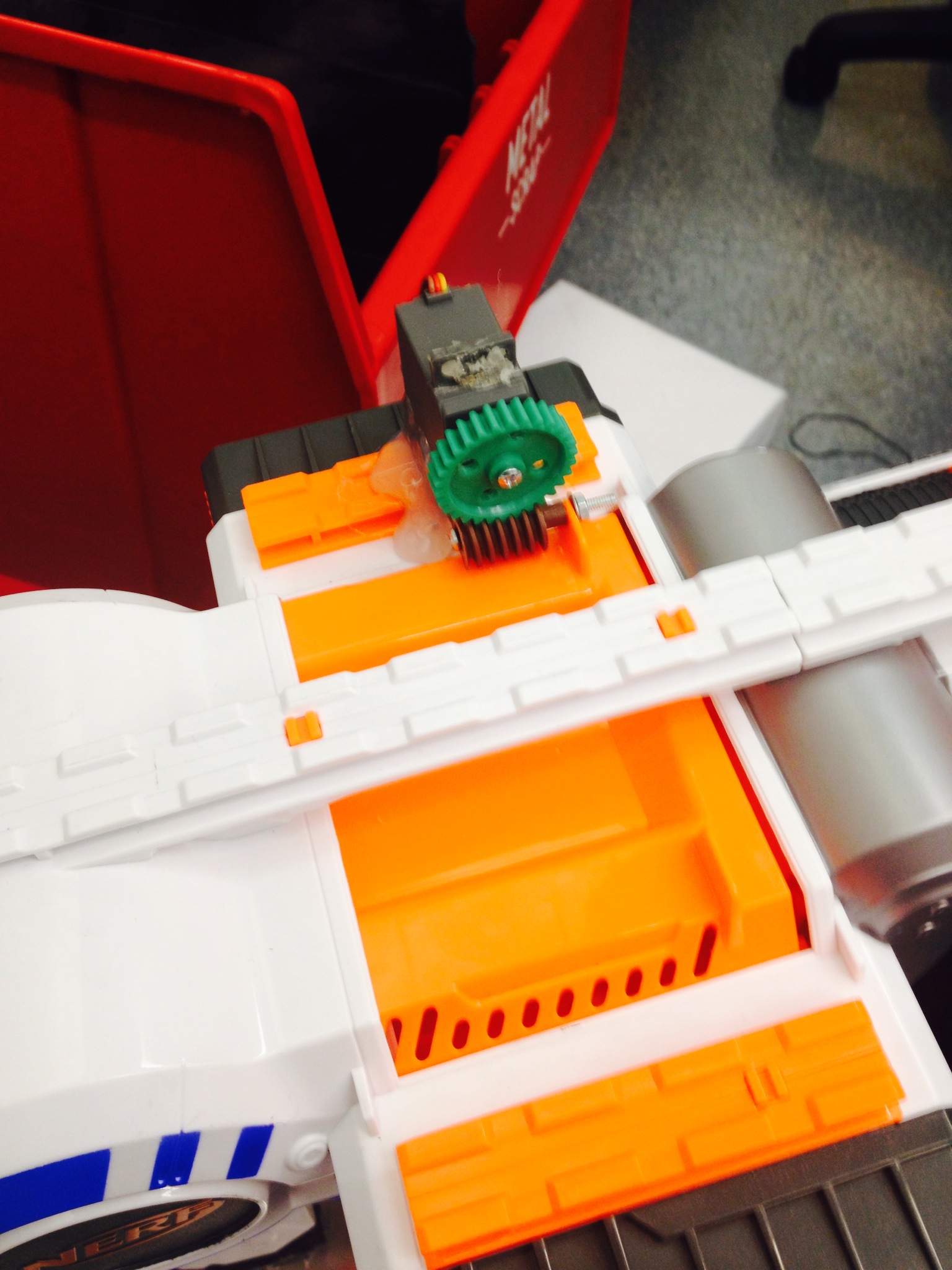
Sprint 3: At this point, we were spending a lot of time figuring out how to hook everything up together inside of our big metal box. We worked on acquiring motor controllers and batteries, and learning how to wire those together. For the claw, all planar parts were laser cut from acrylic and awaited assembly with appropriate belts and belt sprockets. A push to not further overextend the budget and to include all the components in a timely manner, sprockets were designed to be 3D printed. We added the ability to make the robot move faster or slower, depending on the input signal. We also improved the tracking code by making our Kinect wrapper more flexible for any callback function supplied for use with the camera data. Another system integration attempt was made this sprint and the result was that we needed fuses to provide a safer and more fixable failure mode to the system. Multiple trips to the electrical hardware store were made to have a working and integrated system. Sprint 4: In this final sprint, our team finalized and integrated all of our discrete systems. We had already acquired the last parts needed to fully wire up the motors (i.e. breakers and fuses), and were able to run the system - now without a motor shield. In this test, we were able to automatically send commands to the motors based on the Kinect's vision and the comupter's decisions. The system responded properly but we neglected to document that success in video. Unfortunately, We finished 3D printing and mounting our robot's treads, allowing us to test that the motors could make the robot move properly. We worked on redoing the Arduino code to work without a motor shield, so that it would be able to drive the robot via the new wiring. The NERF gun attachment finally arrived and was modified so that it could be triggered by a rack and pinion system, to be controlled by Arduino. 
Finally, we integrated our NERF gun attachment and assembled the claw (just short of installation), to provide options in case of With each of these systems finalized, we combined them for the final product: 
Reflections: After we finalized our integration of everything and took stock of what we had, we reviewed the output this project. We were not able to fully complete a moving and integrated system even though we had already reached our Minimum Viable Product in theory by the start of Sprint 4 with the responding drivetrain. We realized that too much of our work was done within each subsystem, without properly testing how they interact with each other until it was too late. In order to fix this, we should have pushed for complete integration from the start, rather than splitting everything up into subsystems. Interestingly enough, we tried to get an integrated test each week in the second half of the project period but multiple failures within electrical hardware brought forth hindrances to progress in auxillary projects like the claw and NERF gun attachment. One such issue with the auxillary attachments was NERF gun's servo not being strong enough to pull the trigger. This could have been avoided if we had started the attachments earlier. One team goal was to make the product using traditional machining tools whenever possible and to avoid non-scalable processes like 3D printing. As a consideration to cosr and time, we decided to buy our sprockets and print our belts in kevlar and nylon, providing a strong design and use for the new technology. Instead, perhaps we should have printed sprockets and buy belts to save money. |
 RSS Feed