With the eminent zombie apocalypse upon us, SkyWeb’s newest product provides comfort and security for the casual zombie evader up to the avid hunter. How does the ZK-15 operate? It uses state-of-the-art technology to analyze the position and body language of any potential target in order to make an informed and safe action to protect you.
Mechanical Subsystem:
Electrical Subsystem:
 \
\
Software Subsystem:
All code for this project can be found on GitHub
Budget:
Materials
Sketches of the robot in very early stages. Notable features include tank drive via an Arduino, computer vision via a Kinect, accomodation for a number of addons, and a laptop for powerful processing.
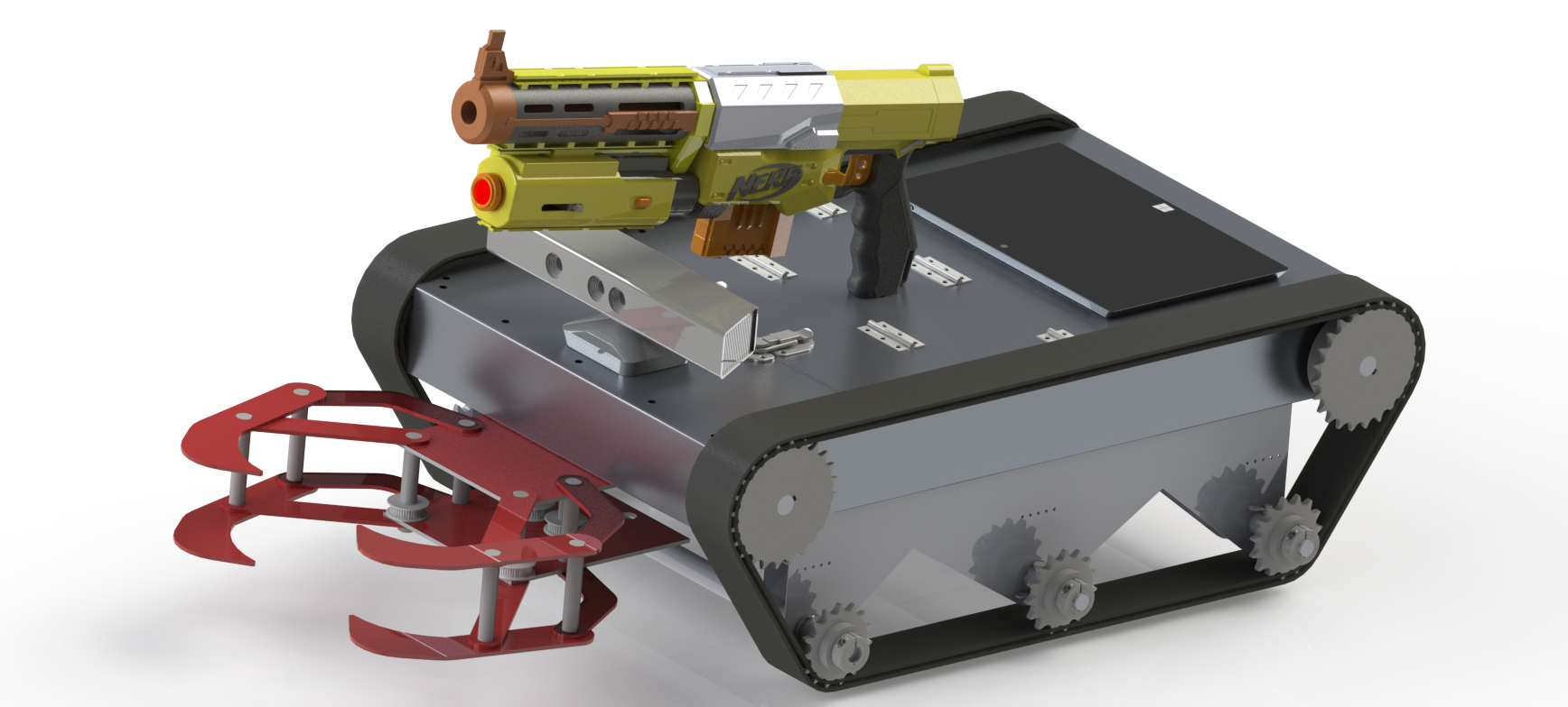
Mechanical Subsystem:
- The mechanical subsystem is composed of 4 main components: the chassis, the drive train, the sentry, and the claw. Each of these systems integrates with both software and electrical components in order to allow the ZK-15 to react according to the threat level it detects.
- The chassis is a predominantly sheet metal construction. The main housing is made from a single sheet that has been hammered into shape.
- This subsystem consists of two main parts: the main chassis housing “tub” and the the bottom shaft standoffs. Most of the components were fabricated from 0.032 in thick aluminum sheet.
- The integration of drivetrain and chassis is achieved through the milled gearbox clock cage. This component was milled from a 2 inch piece of aluminum square tubing, this allowed for a guaranteed rigid precise part that would effectively house all the components for the gearbox as well as tether the motor to the chassis and bracing.
- Finally, the defense mechanism is a separate system bolted onto the chassis. This allowed for more room for iteration and parallel construction as we could build the chassis before the components were finalized.
- The turret is an off-the-shelf NERF product; it was chosen not only because of its electronic automatization (removing the need for a cocking mechanism) but also because its tripod allowed it to sit above the Kinect camera and for it to be mounted without interferences.
- Treaded vehicles are difficult to design. They require a lot of forethought into the torque needed for the vehicle to move effectively. When designing this vehicle we encountered a seemingly unsurmountable obstacle.
- In our first iteration we were able to buy our wheels, sprockets and belts from a toy company. However, once we obtained the necessary dimensions for the full scale robot we found it hard to find belts and pulleys within our price range.
- In order to sidestep this issue, we decided to buy the much more affordable sprockets and to 3D print our treads in kevlar and nylon using the state of the art Markforged MK1 3D printer. As far as we know, nothing of the sort had ever been attempted and we decided to give it a shot based on a print that failed after laying down just a couple layers of nylon and a single one of kevlar seemed to be flexible and very strong.
- We were only able to print sections of 10 inches at a time therefore we had to link 6 prints together to form a belt of the correct size for our robot.
Electrical Subsystem:
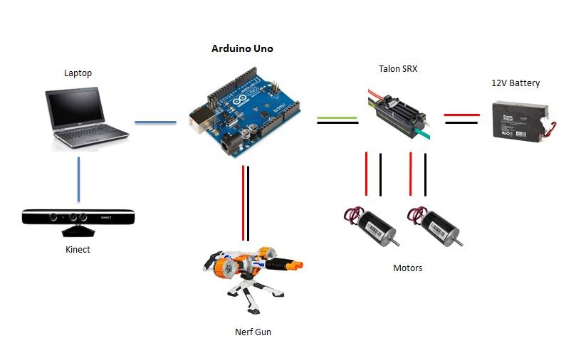
- Our electrical system is composed of an Arduino linked up to a laptop, sending PWM signal to two motor controllers powered by 12V batteries connected to two motors which power the gearbox.
- To create this system we started by soldering and heat shrinking all wires not directly connected to power, as well as the wires that need to be connected to gator clips for attachment to the power supply; for any extra wire needed we used 12 gauge wires for consistency.
- The wires not directly connected to power included the ground and power of the motors which connected to the power out and ground of the Talon SRX motor controllers, and the wires that needed to be attached to gator clips included the power and ground wires of the motor controllers.
- When connecting the power of the motor controller to the gator clips we included a slow blow 12V 12A fuse to account for any occasional surges.
- Finally, we connected the PWM signal wires on the motor controllers directly to the Arduino for RC instructions.
- With our final setup, we were able to test the code written with our electrical system where the motors would spin based on Kinect input.
- Through this portion of testing, we managed to break one Talon because of reverse polarity. When this happened, we managed to change the setup of our electrical system to run both motors off of one motor controller by connecting both motor's powers to power out on the motor controller, which split voltage but did ultimately work.
- This new set up limited movement to rotation about the robot’s central axis and rotated based on the target's location from the Kinect.
- Unfortunately, we managed to break the second Talon by hooking the motors up to the mechanical gearbox system. We’re not entirely sure what caused the second motor controller to break, but we believe that too much torque was applied to the motors, causing a surge back into the motor controller from the motor itself.
- Given these iterations we find that the electrical system could improve upon protection against surges, but worked overall when properly set up.
\
Depiction of the electrical interactions within the entire system. Red lines indicate power, black lines indicate ground, green line indicate signal between motor controller and Aruino and blue lines indicate computing signals interfacing between the Kinect and laptop.
Software Subsystem:
All code for this project can be found on GitHub
- We initially focused on writing Arduino code for moving the motors via a motor shield.
- The next step was adding serial communication parsing so that the robot would follow instructions sent from another program.
- After that, we started writing the Python program that would become the controller for instruction signal sending.
- Once we were satisfied that we could move our small test robot with keypresses on a laptop, we started looking into target detection with OpenCV.
- After some less-than-satisfactory human detection results, we decided to take advantage of that fact that our camera was a Kinect and use their skeleton tracking API.
- We then spent some time learning about (and writing a wrapper for) Microsoft's Python implementation of their Kinect API.
- After we combined the Kinect data processing code with the serial communication code, we had a little robot that moved according to what the Kinect saw!
- Next, we added some body position recognition using the Kinect skeleton position data. The robot now designates you as friendly if your hands are on your head, or a foe if your arms are raised in front of you like a zombie.
- Finally, we went back to change the Arduino code for servos instead of a motor shield, since the motor shield was messing with the motor controller calibration.
Demonstration of the signal processing and instruction calculation from Kinect data.
Budget:
Materials
- 0.032in thick aluminium
- 4x 4in sprockets
- 6x 2in sprockets
- 0.75in precision ground aluminum rod
- 0.625in precision ground aluminum rod
- nylon bushings for 0.625in and 0.75in shafts
- 2x CIM motors
- 2x go-kart batteries
- 2x Talon SRX motor controllers
- 6x 0.625in shaft collars
- NERF Rhino-fire elite turret
- 0.25in clear polycarbonate sheet
- 2 in 0.25 wall thick square aluminum stock
- Gorilla tape
- Batteries: $29.33
- Charger: $15.99
- Breaker: $8.01
- Vex Robotics: $207.25
- Vex Robotics: $70.90
- Vex Robotics: $41.24
- Online Metals: $28.64
- Vex Robotics: $41.72
- Vex Robotics: $72.10
- McMaster: $16.86
- McMaster: $29.94
- McMaster: $9.35
- McMaster: $34.54
- McMaster: $20.01
- McMaster: $71.46
- McMaster: $19.34
- McMaster: $119.07
- McMaster: $87.11
- McMaster: $411.83